

I R A Gadget Maker, R U?
UV based caches are common, let's go the other direction

This is a quick little build using some parts I had around the workbench. This build was inspired by using a cheap CCD camera to check the output of a TV remote. Knowing that cheap cameras and most cell phones would show the otherwise invisible to the human eye IR (infrared) wavelengths, I set out to build a tiny puzzle.
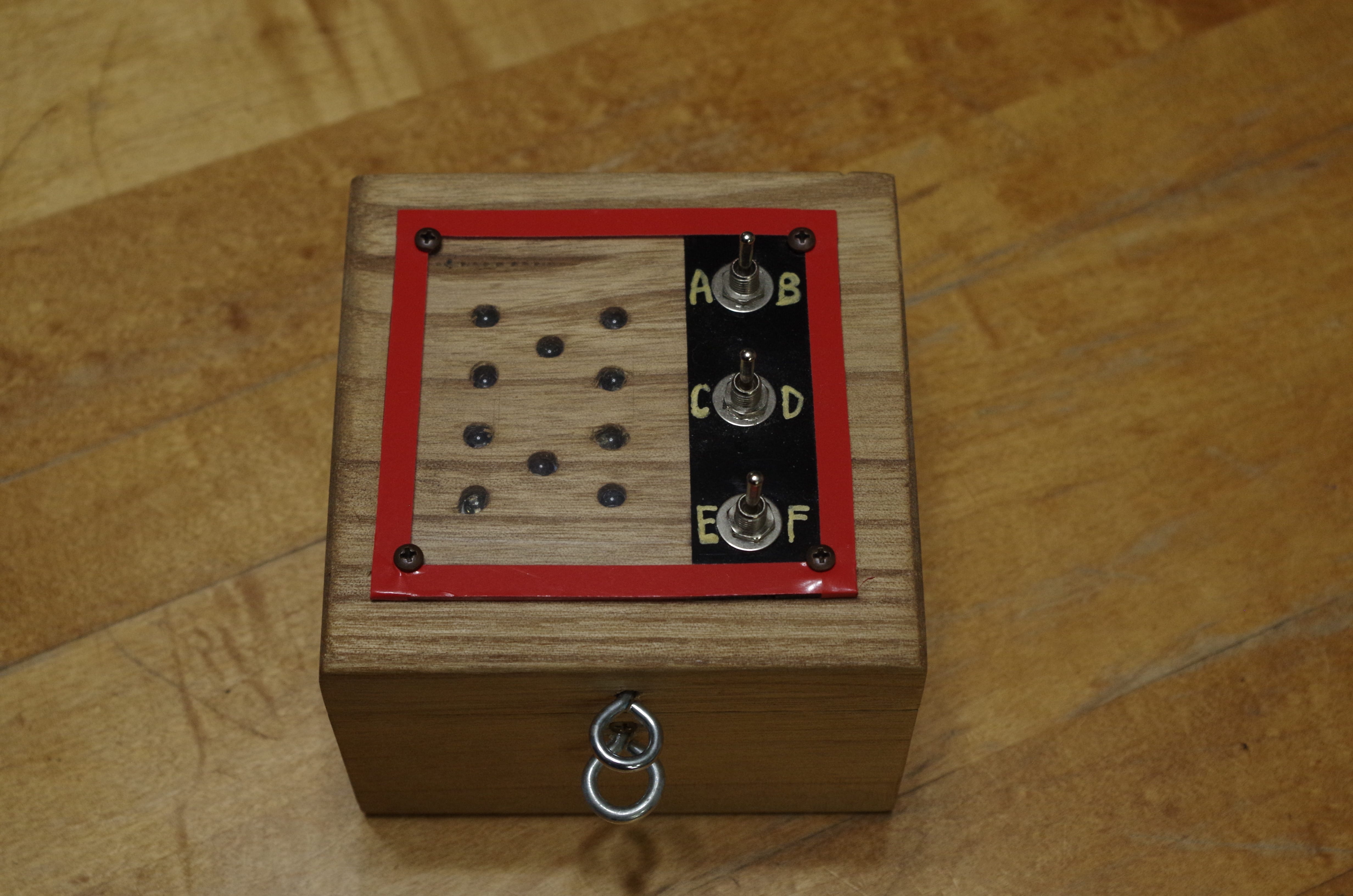
The entire puzzle is made from LEDs, switches, a buzzer, and a wooden box. Looking at the schematic you can see that each switch position does something. Nothing tricky in the wiring for this one.
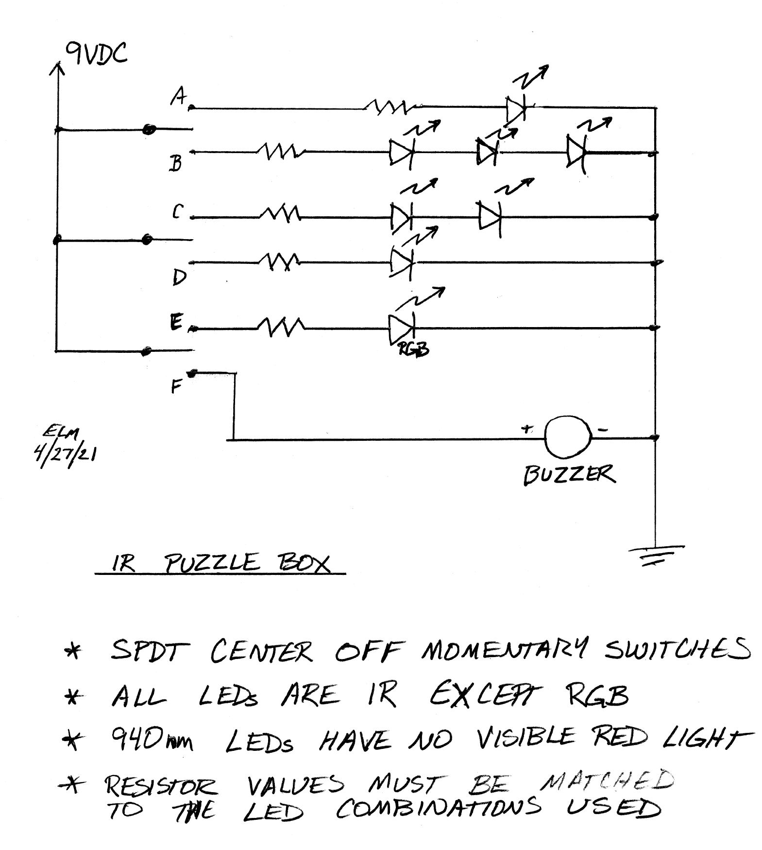
Each switch is a center off, momentary with spring return, two position switch. This lets us get 6 different switch actions from 3 devices. The third switch, positions E and F, is the red herring in this puzzle. Position E activates a pretty red/green/blue flashing LED. The LED changes patterns as it flashes, hopefully making solvers try to discover a pattern. Position F makes a buzzer sound.
It is important to use the correct IR LEDs for this project. 940nm wavelength LEDs are completely invisible to the human eye. Other IR LEDs are available that give more IR output but they can have a dull red glow by eye, making them not suitable for this kind of puzzle. Remember to use the correct resistors to protect your LED combinations for the battery voltage you use.
By eye, the puzzle appears to have two non-functioning switches. Here’s a video of it made using a camera with an IR filter. Unsolved Video
Using a cell phone or other camera without an IR filter reveals the combination for the padlock. Solved Video
This general idea can be expanded to make more complex puzzles. Using an Arduino to drive the LED when triggered can allow the IR LED to blink codes, for example. Look for one of those in a future build.