

I See the Light - LEDs
Tech Tuesday is all about using LEDs

LEDs, or Light Emitting Diodes, are the usual way to have elements that illuminate in gadget caches. LEDs use little power, run cool, and last a long time. They come in many different colors, including IR or UV outside the visible light spectrum. Add wide availability and low cost and they make an excellent device for our builds. There are a few things to consider when using LEDS so they live a long life in your projects.
Incandescent light bulbs are simple voltage devices. Match the voltage to the rating of the light bulb and it works. Lower the voltage and the light dims. Raise the voltage and the light gets brighter – until the filament fails and the bulb burns out. Polarity is not important, the bulb lights with the battery in either direction.
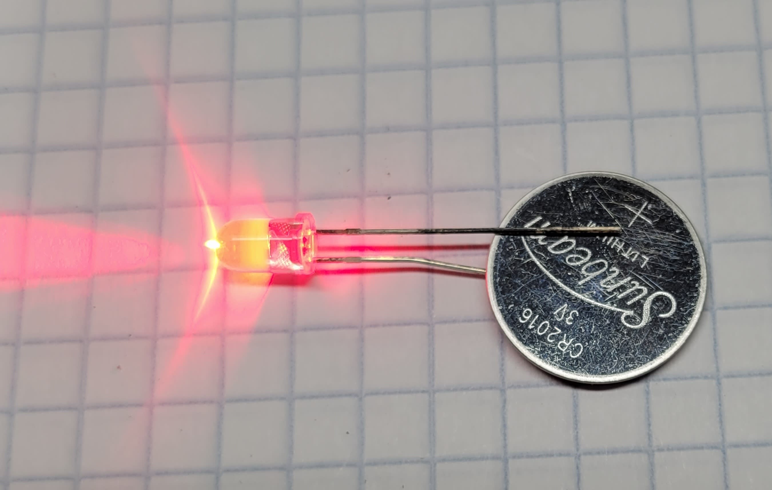
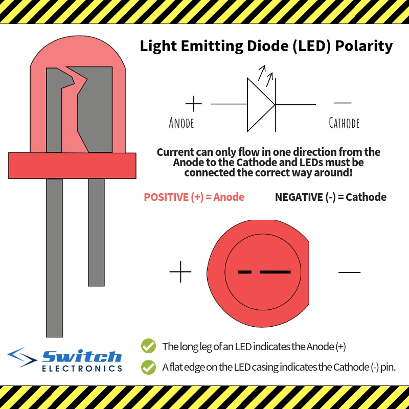
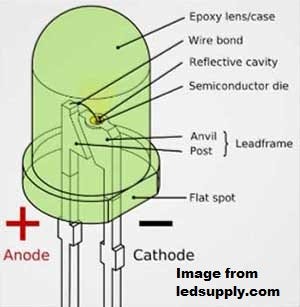
LEDs only work when voltage is applied the right direction. How do we tell when connecting the LED? There are a few different ways. The plastic case of a typical 5mm LED has a flat side indicating the negative connection. If you can see inside the plastic case, the larger metal piece inside is the negative side. If the LED has two different length wire leads, the longer one is the positive side. The following images from Switch Electronics and LEDSupply show these characteristics. But if all else fails, you can make a quick check with a small coin cell battery. You must use this kind of battery because its current capability is so low it won’t output enough to harm the LED. Just use the coin cell between the LED’s leads as shown in the opening photo and see which battery polarity makes the LED light.
LEDs are not voltage dependent like incandescent bulbs. LEDs are current dependent. That means the current through the LED, not the voltage across it, sets the brightness. The voltage across the LED remains constant as the current changes. LEDs require some way to limit the current through them or they will be damaged. We must determine how to set the current through the LED. First, we’re going to talk about electronics theory and do some calculations. Don’t worry, we will then discuss how to use some simple tools to avoid doing those calculations.
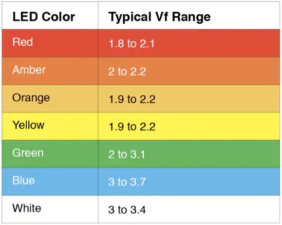
Since the voltage measured across the LED stays constant as we vary the brightness by changing the current through the LED, we can use Ohm’s Law to determine the proper resistor to limit the current as needed. Different colors and types of LEDs have different forward voltages. When using a LED in a project, start with the maximum current rating and the forward voltage of the LED. If you don’t know the ratings for your LED, you can make some safe assumptions. Typical 5mm LEDs are good for 20mA of current through them for maximum brightness. The voltage varies with color, with this table serving as a good reference.
Now that we know the voltage across the LED, and the current through the LED, we can decide what resistor to use based on the circuit voltage.
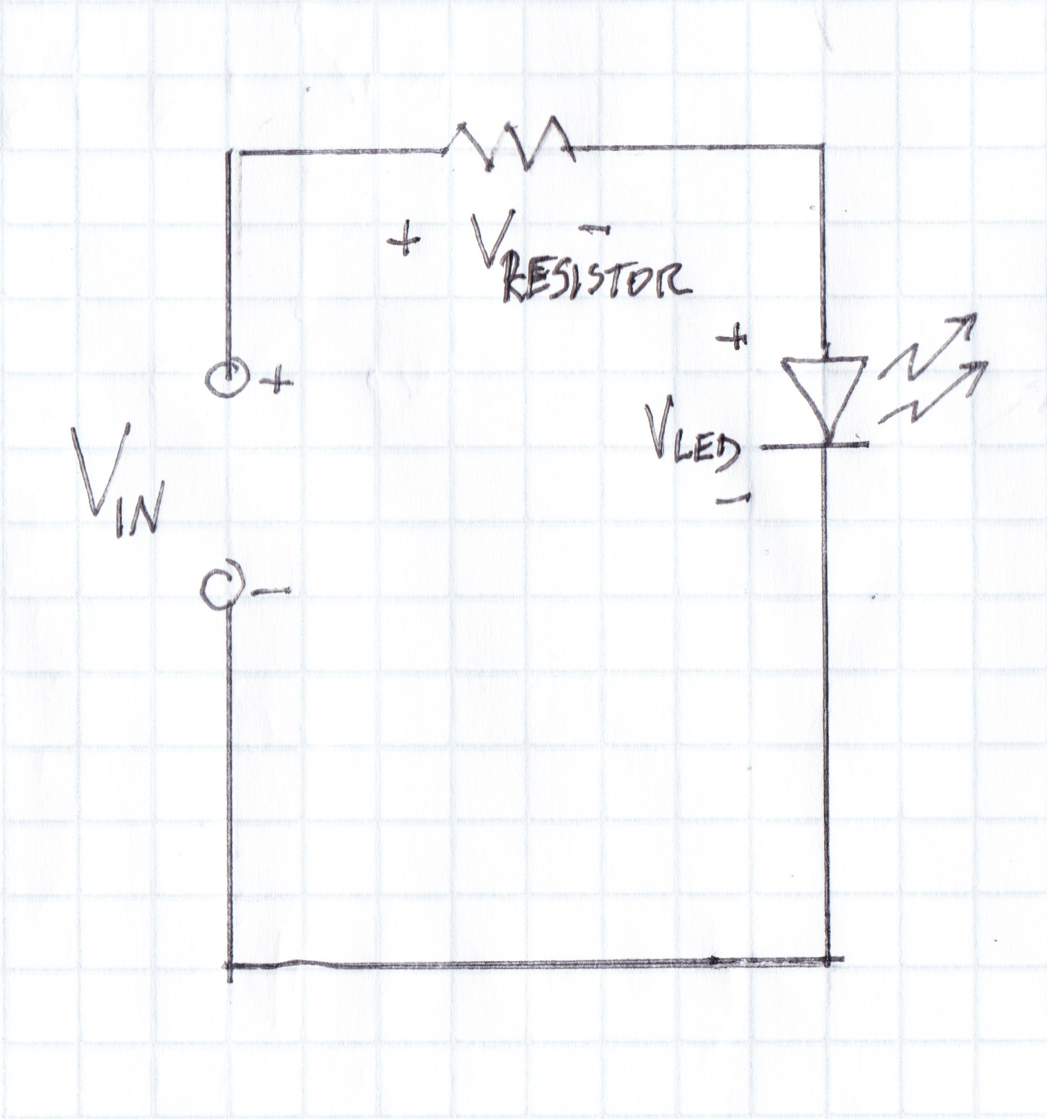
This circuit shows a simple circuit of a battery, current limiting resistor, and LED. Basic laws of electronics state:
The current through all devices in a series circuit is the same. 20mA through the LED also means 20mA through the resistor.
The voltage across the resistor and the voltage across the LED must add to the voltage of the source.
Our Maker Magic event gadget uses a 9V battery and a blue LED. Looking at the table, we can see the LED’s forward voltage will be 3 to 3.7 volts. The datasheet for my blue LED says 3.0 to 3.2V at 20mA, which is in the rage of the general table. We will use 3V.
Remember we said that the voltage across the resistor and the voltage across the LED need to add to the voltage of the source? That means the voltage across the resistor plus 3 volts across the LED must equal 9 volts. Or, we can say the voltage across the resistor is
9-3=6 voltsWe also know that the current through the LED will be 20mA. That makes the current through the resistor 20mA as well. What size resistor will give us 20mA through it with 6 volts drop across that resistor? Time for Ohm’s Law.
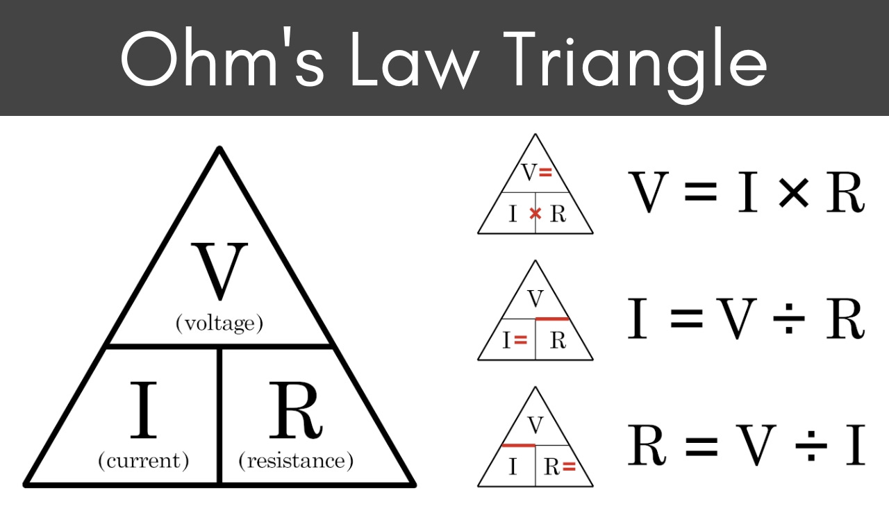
Using the equation Volts (V) = Current (I) X Resistance (R), we can rearrange the terms to say Resistance = Volts/Current. Fill in the values to get
Resistance = 6/0.020 = 300 ohms We need a 300 ohm resistor for that blue LED for full brightness.
But what if we want to light two LEDs? One way is to give each its own current limiting resistor and connect each set to the battery. Another is to remember that the current through items in series is the same and place two LEDs in series with one limiting resistor. If we do this using two of our blue LEDs, we will have
9-3-3=3V across the resistor3/0.020=150 ohmsNow we know how to choose the correct resistor for any LED. In the gadget we used a 330 ohm resistor and not the 300 ohm from our calculations because that’s the part I had. The resulting small reduction in current through the LED makes a barely noticeable difference in brightness. Feel free to experiment with different resistors if you do not go beyond the maximum rating of the LED. If you purchase LEDs with resistors already attached designed for 12V they will probably still work fine at 9V, but they might be dim at 3V.
One last thing to keep in mind. Voltage and current at the LED are turning that energy into light. At the resistor that power is turned into heat. It is possible to create excessive heat in the current limiting resistor. Consider an extreme case of a 24V source with a single 2V red LED.
24-2=22Vacross the resistor tells us we need a 1100 ohm resistor. Power is voltage times current, so we will be releasing
22x.020=0.44Was heat from the resistor. That’s nearly half a watt. Small resistors might be only 1/8 or 1/4 watt rated. In most cases building gadgets power dissipation won’t be an issue but keep it in mind.
Did you break out the calculator or pencil and paper to work along with these examples? While important to understand what is happening, there are many tools online or as apps to avoid doing the calculations. In Android, I like using Electrodoc. They have an Apple version too. Online, these are some good examples:
If you need help identifying your resistors by color, this tool may help. Or you can just remember “better be right or your great big venture goes west”. Yes, there are other mnemonic devices for the resistor color codes. No, we don’t need to share them in the comments.
Now that we can light a LED with switches, we are ready to build the gadget cache. Next time, we will go through making the example gadget from the Maker Magic event.
Want more tech articles like this? Too deep and you want to see more builds without theory? Let me know in the comments.