
The goal of the Maker Magic event (besides hanging out with lots of other cachers) was to create a real puzzle that anyone could build without deep technical knowledge. I had some criteria in mind:
Inexpensive
No specialized parts
Must be electric/electronic
Required simple soldering
Solution should not be too hard or too easy
Clearly show when the puzzle is solved
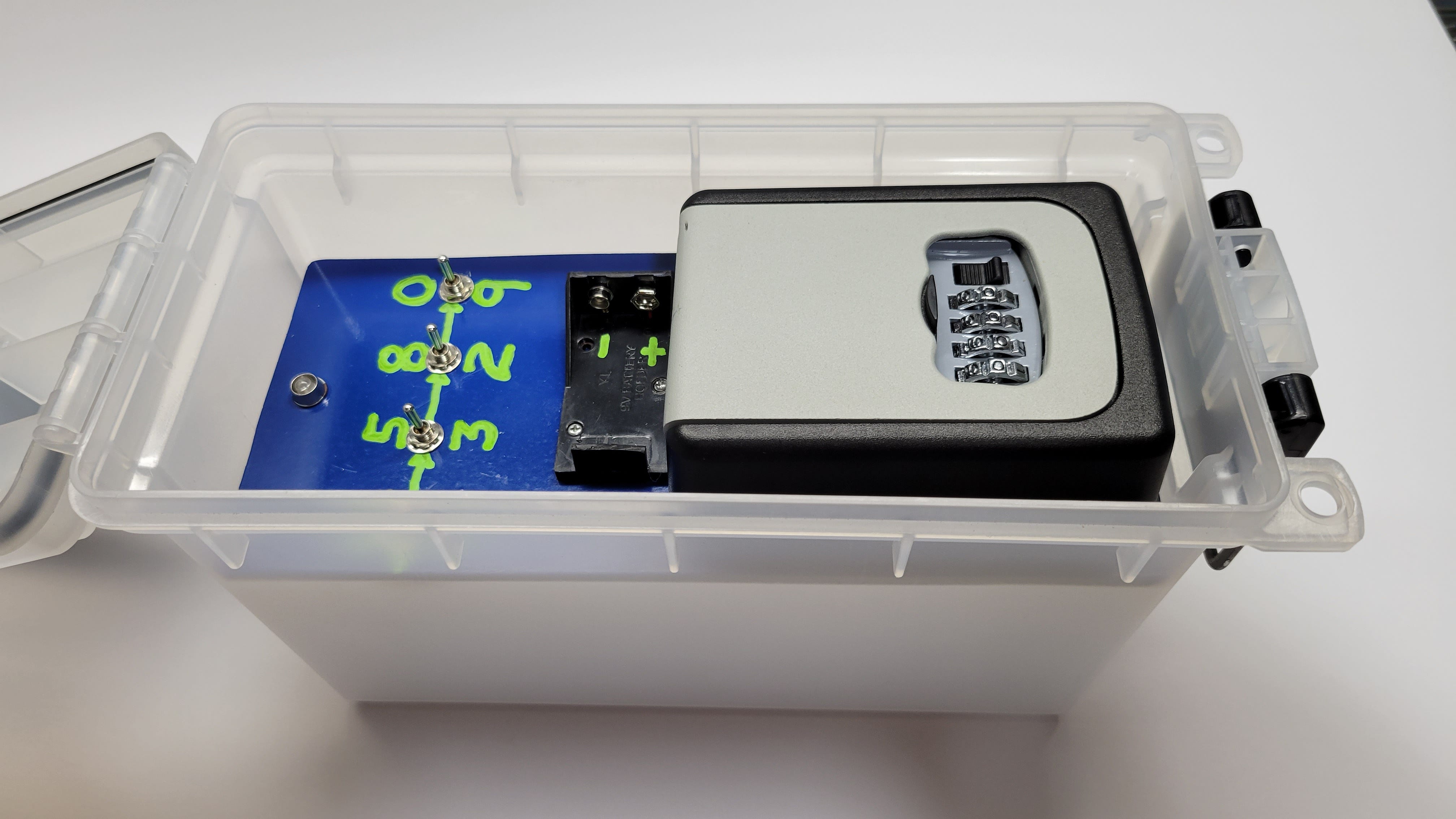
Fit an ammo can with a flat plate insert
Low maintenance (no battery replacements)
Before going into the build, please note that previous Tech Tuesday articles talked about LEDs, switches, and the tools you will need to build this puzzle for yourself.
I found two realtor key lockboxes at a surplus store and decided to use one of them as the log container. I then needed a way to generate the four-digit code needed to open the box. Looking through my parts stash I found enough DPDT center off momentary switches to make a good puzzle. Any kind of switch could be used, and there is no reason all the switches on the puzzle need to be the same kind. I do suggest using momentary switches so that the cache can’t be left in the solved state if a finder fails to reset the switches. I could have used a many different devices, but I chose a very bright blue LED as the signal the puzzle was solved. All this would go inside an ammo can to keep it safe and dry.
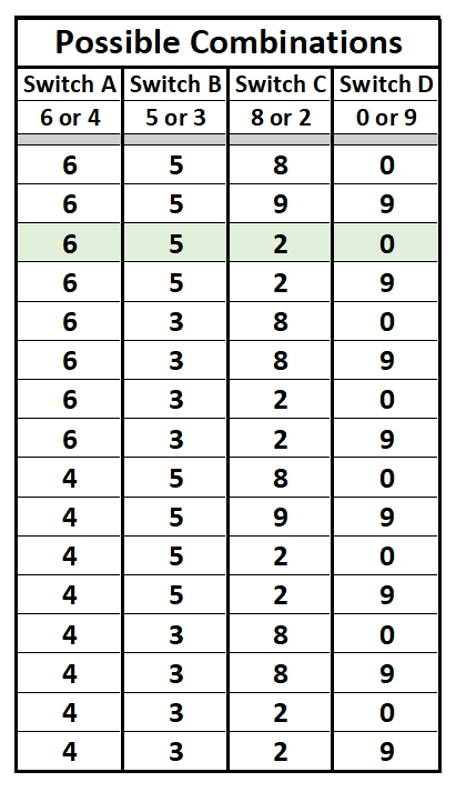
Four of these switches seemed a good balance between too easy and too hard. Three-digit locks don’t take long to try all the combinations. Four digits are better for cache puzzles. At the same time, geocachers don’t want to try hundreds of switch combinations. I could have used each of the four switches with 3, 4, 5, or more positions. A finder would run out of patience long before the combination might be found. Using double pole switches gives a reasonable table of possible combinations:
I started with a square of plastic/aluminum composite material and cut it to shape for an ammo can insert. All components mounted to this plate with fasteners. I like this plastic material with thin aluminum on each side because it is easy to cut, drill, and paint. This plate fits into a plastic ammo can.
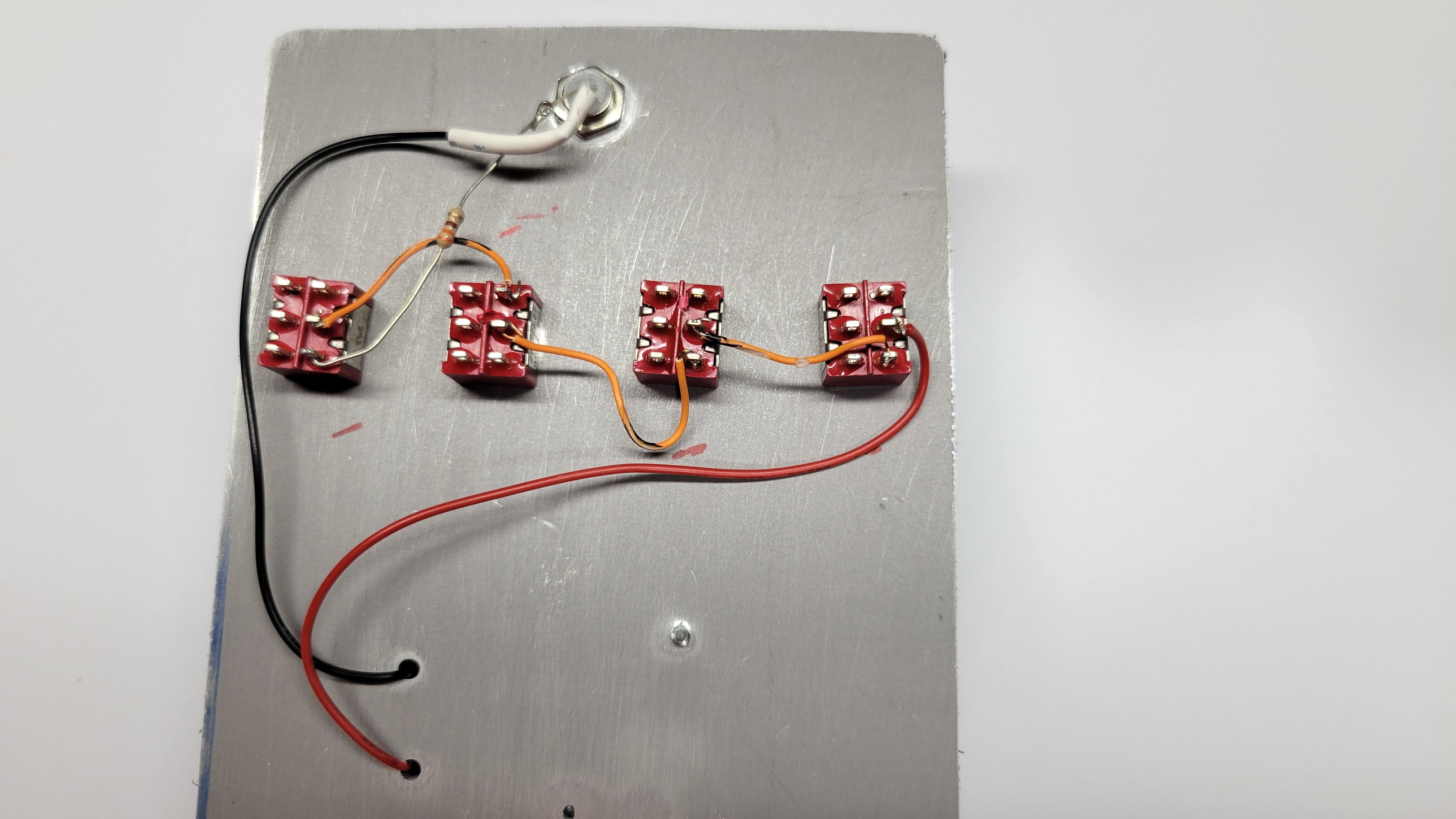
Each of the switches is off at rest, with the lever in the center. Each switch can be either up or down to select between its two outputs. These are DPDT switches, but we are only using one pole (green box on the image) so SPDT would work as well. The second pole remains unused (yellow box on the image). The center terminal of each switch is common, and the outer terminals are connected when the switch is on.
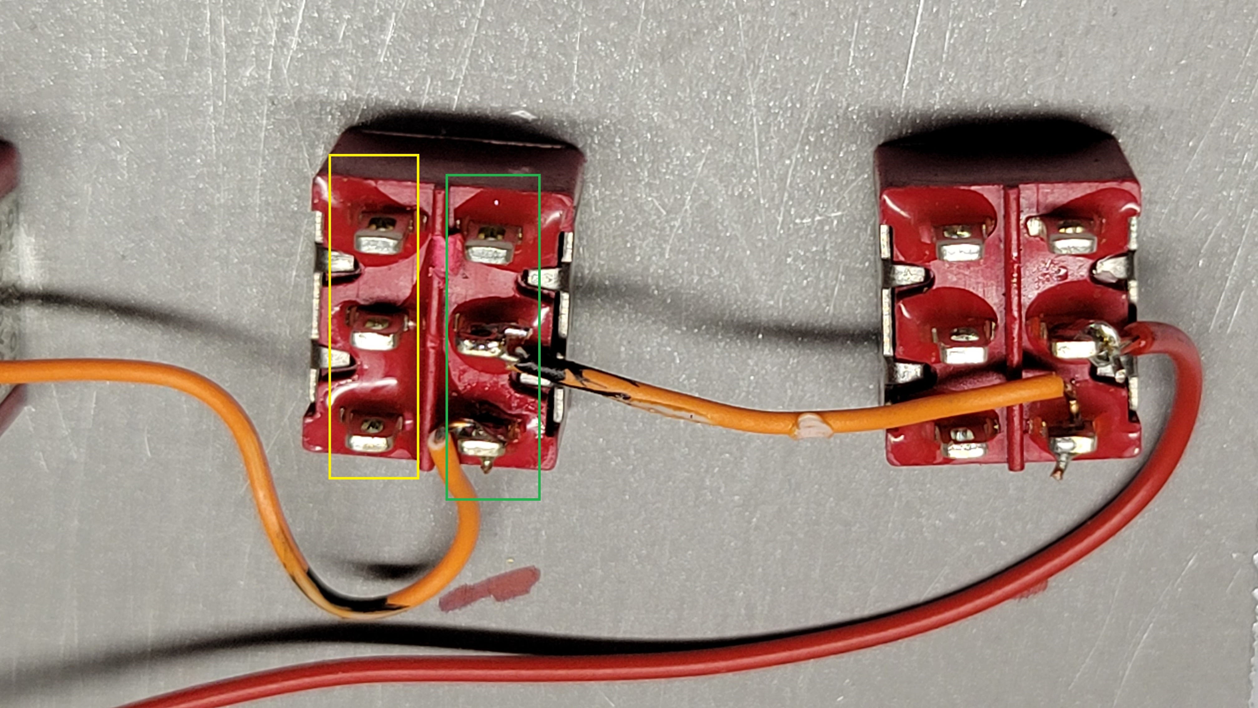
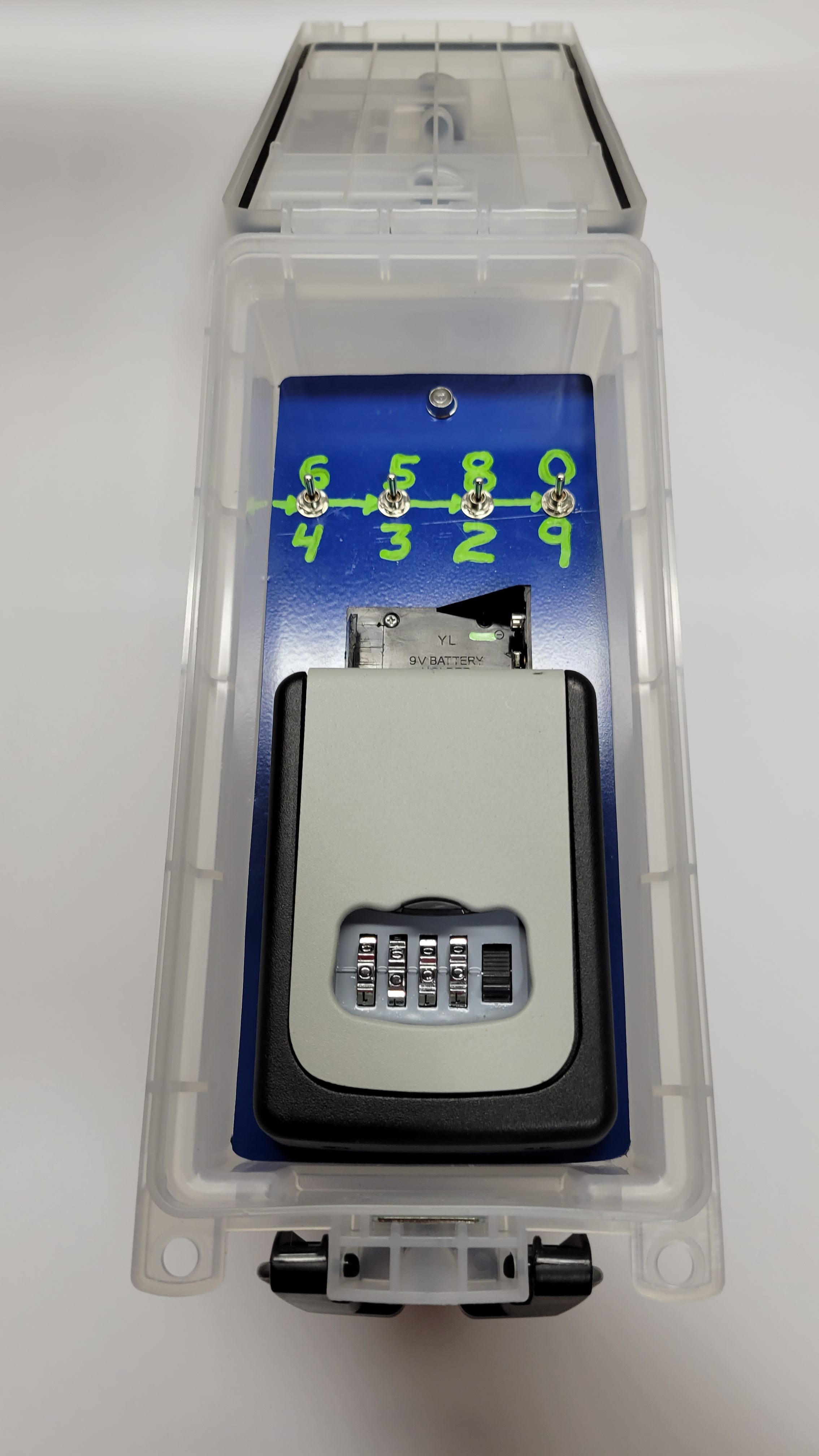
I decided that UP UP DOWN UP would be the combination. I determined which contacts on the switch corresponded to those lever movements and soldered wires between them, each time going from the upper or lower terminal of one switch to the center common terminal of the next. The circuit is complete only when all the switches are in the correct positions. You can see the red marks I made next to each switch to remind me which contacts to use.
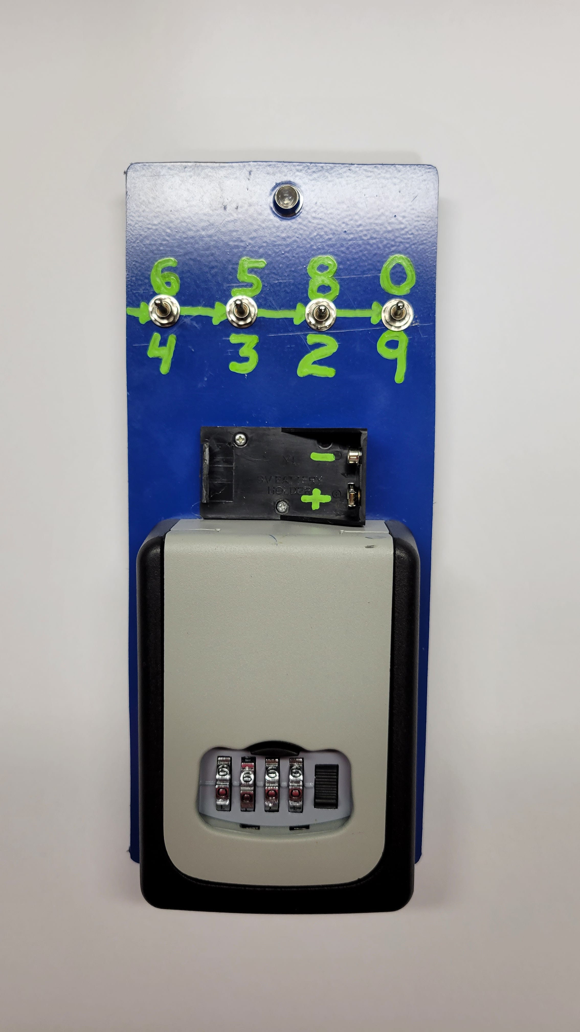
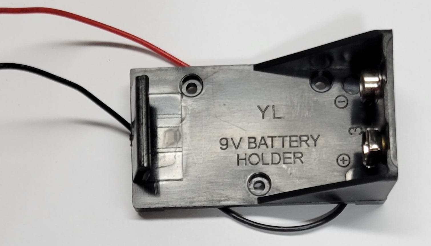
Next, we needed to power the puzzle. I chose a 9V battery because they have holders that are more difficult to connect backwards. This puzzle has very low current requirements, so it was perfect for a 9V battery. I think it is easier for a cacher to carry one 9V battery than a pocket filled with AA or D cells. I soldered the positive battery holder lead to the common terminal of the first switch.
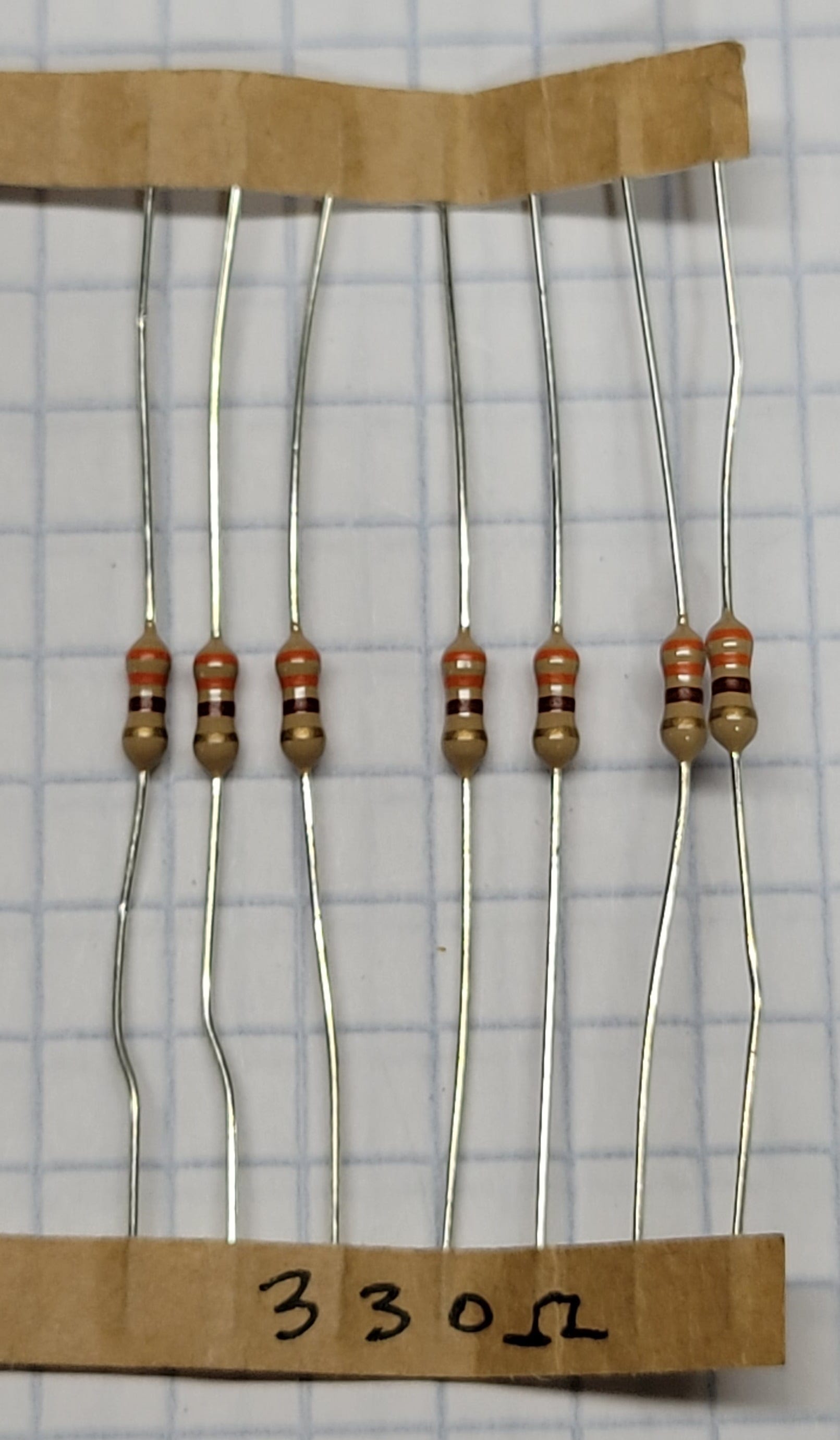
All that remained was the LED. I soldered the negative lead of the battery holder to the negative side of the LED. You can see the white heatshrink tubing I used to insulate that connection. The final connection was from the switches to the positive side of the LED. If you remember the article about LEDs you will know we needed to use a resistor here to set the current through the LED. If you don’t use the resistor, the LED will give one brief flash and be destroyed. Using the calculations previously discussed, a 330-ohm resistor was perfect. With a 9V battery and a led forward voltage of 3.1V we put 18mA through the LED. The orange orange black color codes show the resistor value.
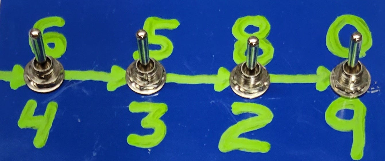
We still needed numbers to make the lock combination. I chose some random numbers and painted them onto the plate. Arrows hint at the order to read the numbers for the solution.
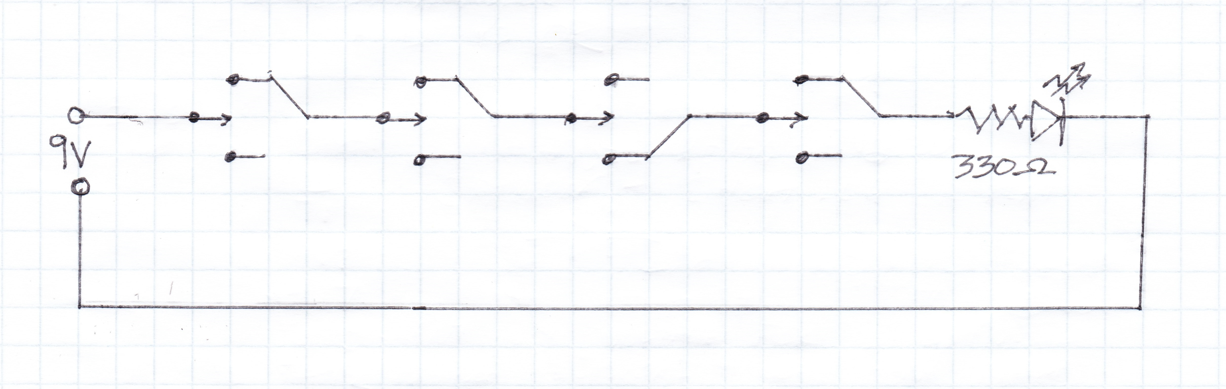
It took many photos and words to describe our simple puzzle circuit. Using a schematic drawing is a much faster way to show what we built. Can you follow the drawing now that we’ve described how it works?
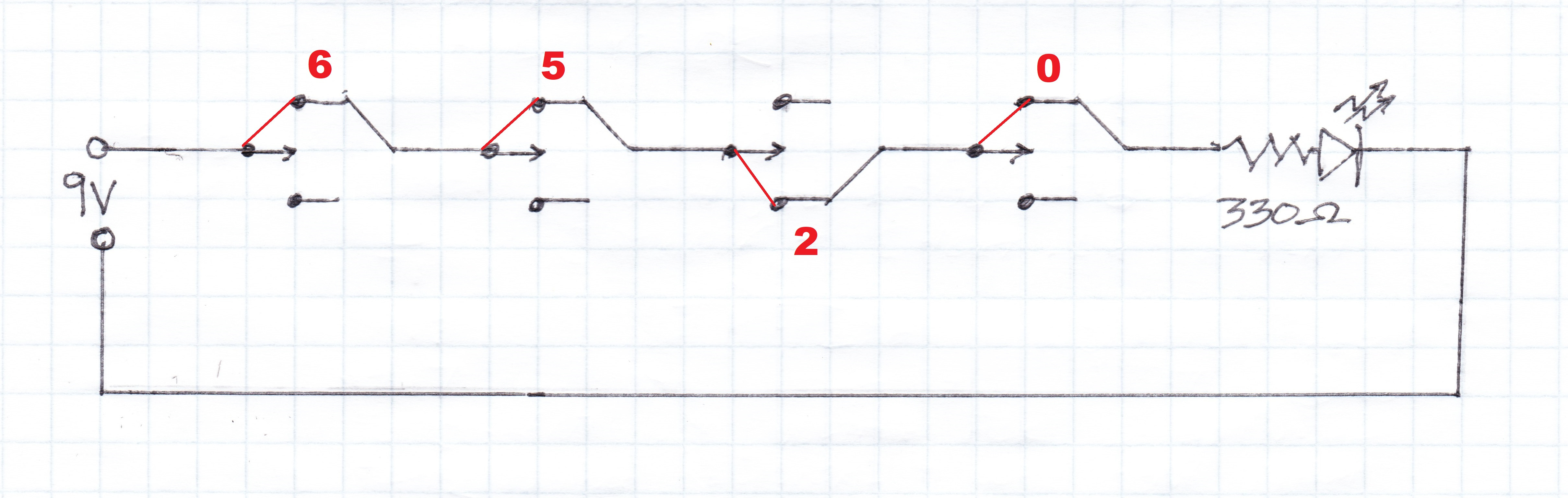
Here is the circuit again, but this time with the numbers and switch positions shown in red for the solution.
The final step was to program the lockbox to open with 6 5 2 0. I recommend you glue or otherwise disable the programming lever so the code is not accidentally changed while in the field. With that the cache was ready to hide.
While this is a very simple puzzle the idea can easily be expanded:
Try different numbers of switches
Change the type of switches used
The unused pole of each switch could turn other things on. Each switch position could light another LED, or play a sound, or whatever you would like.
Change to reed switches so the geocacher is met with a blank plate and must use magnets to turn on the switches.
Add an additional LED that lights to show the battery is in backwards.
Are you going to try building one? Let me know how it turns out. I’d love to see what you build and might even show some in a future article.