Couch Potato?
Geocaching is intended to get you off the couch, but you don't need to put down the remote

A few years ago I helped a Cub Scout day camp build infrared (IR) triggered monster boxes as a project for the youth to take home. They worked great but to keep costs down we used a simple IR sensor. The boxes opened when commanded, but also when sunlight hit the sensors, etc. I knew there was a better way if I increased the budget by a few dollars.
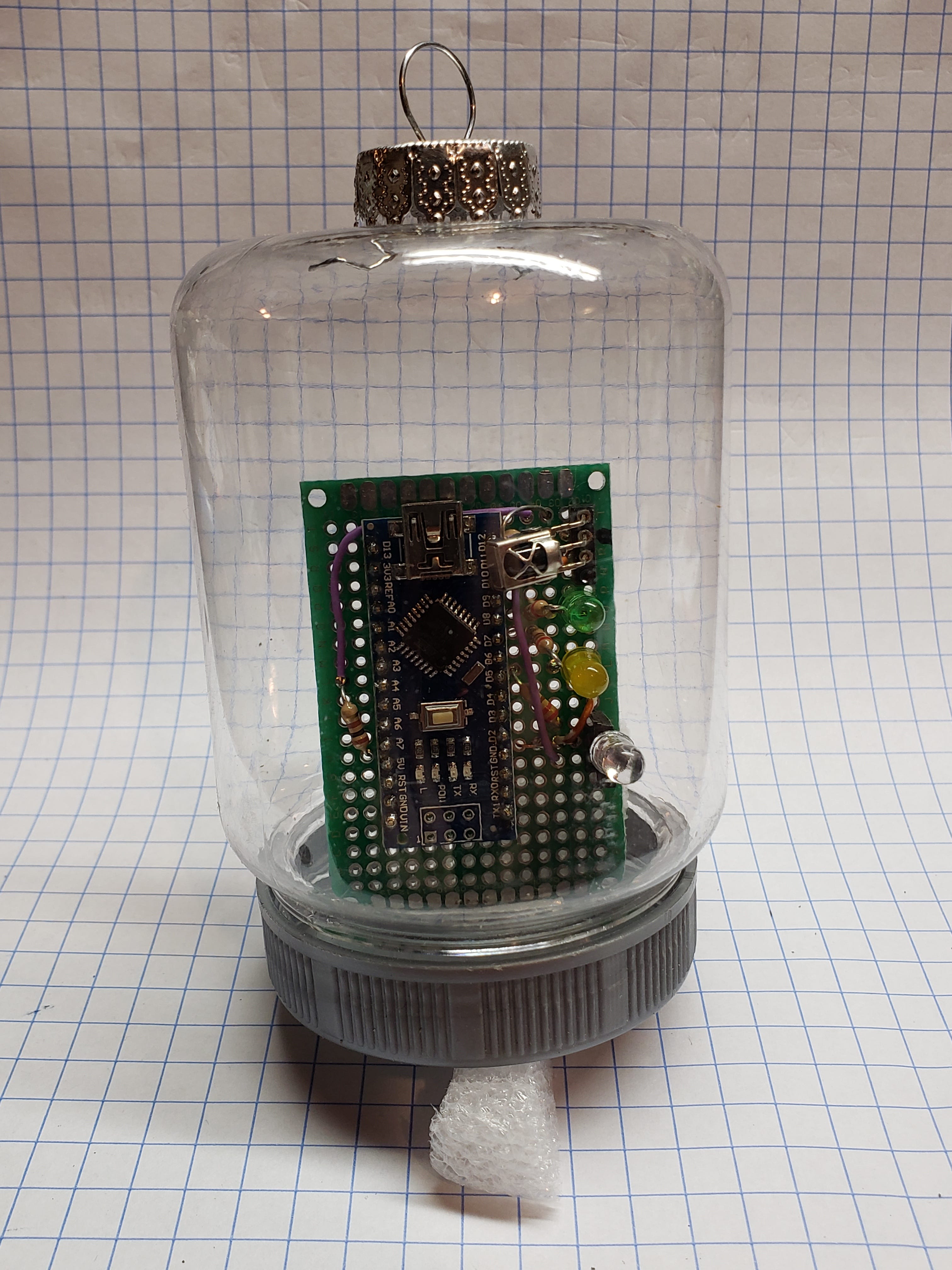
Using a TL1838 IR sensor, found in many remote control receivers, allows the device to only respond to modulated IR light. This means only IR turned on and off at 38kHz will be received, making the circuit immune to sunlight, flashlights, etc. I put together a quick demo circuit with a socket so I could use either a visible or an IR LED. As we saw in an earlier build, infrared light invisible to the human eye can be detected with a cell phone camera. My first idea was to use this a beacon for the first stage of a multi-cache, giving some kind of info for the next stage. I built it inside a hanging container:
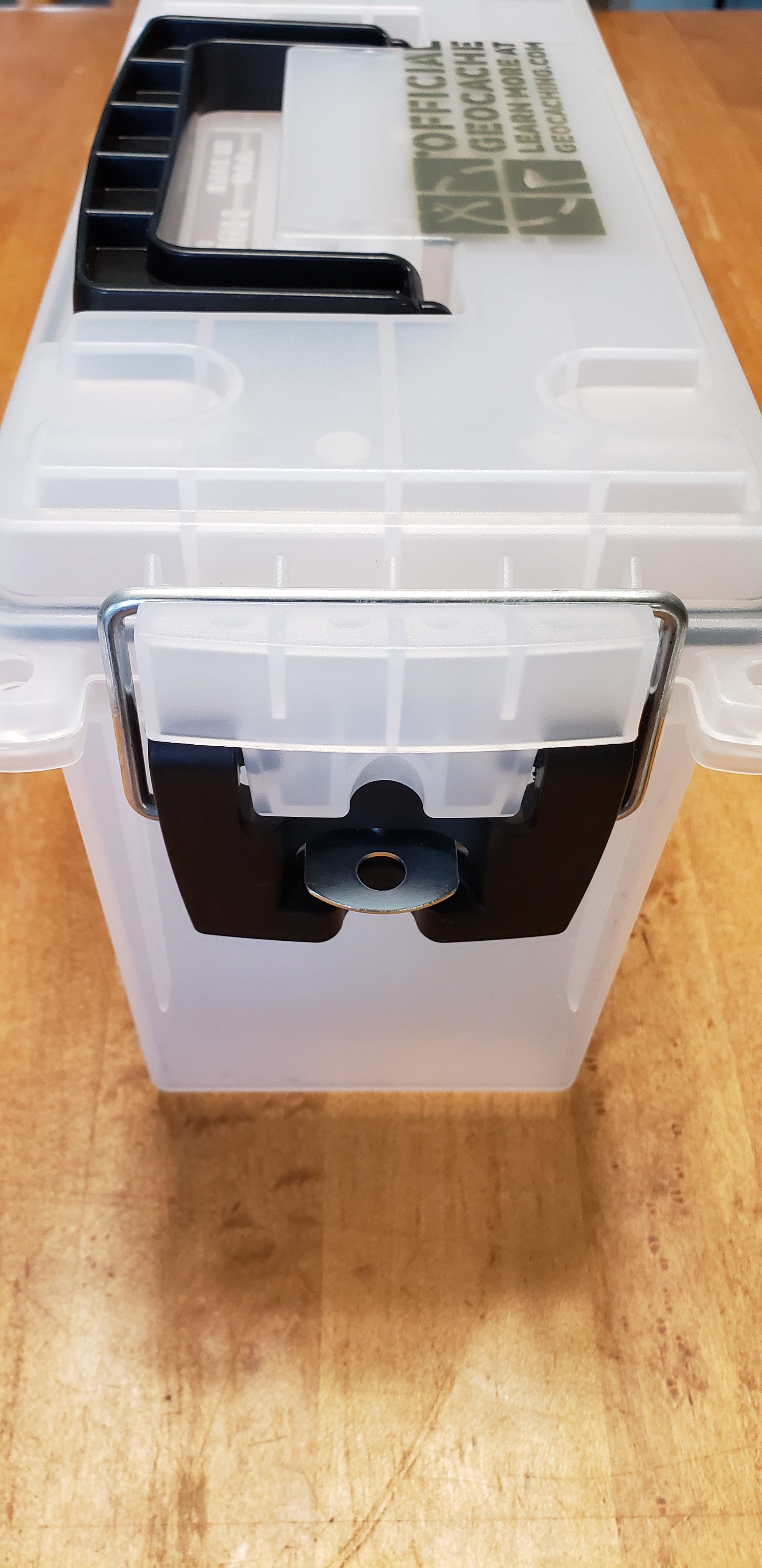
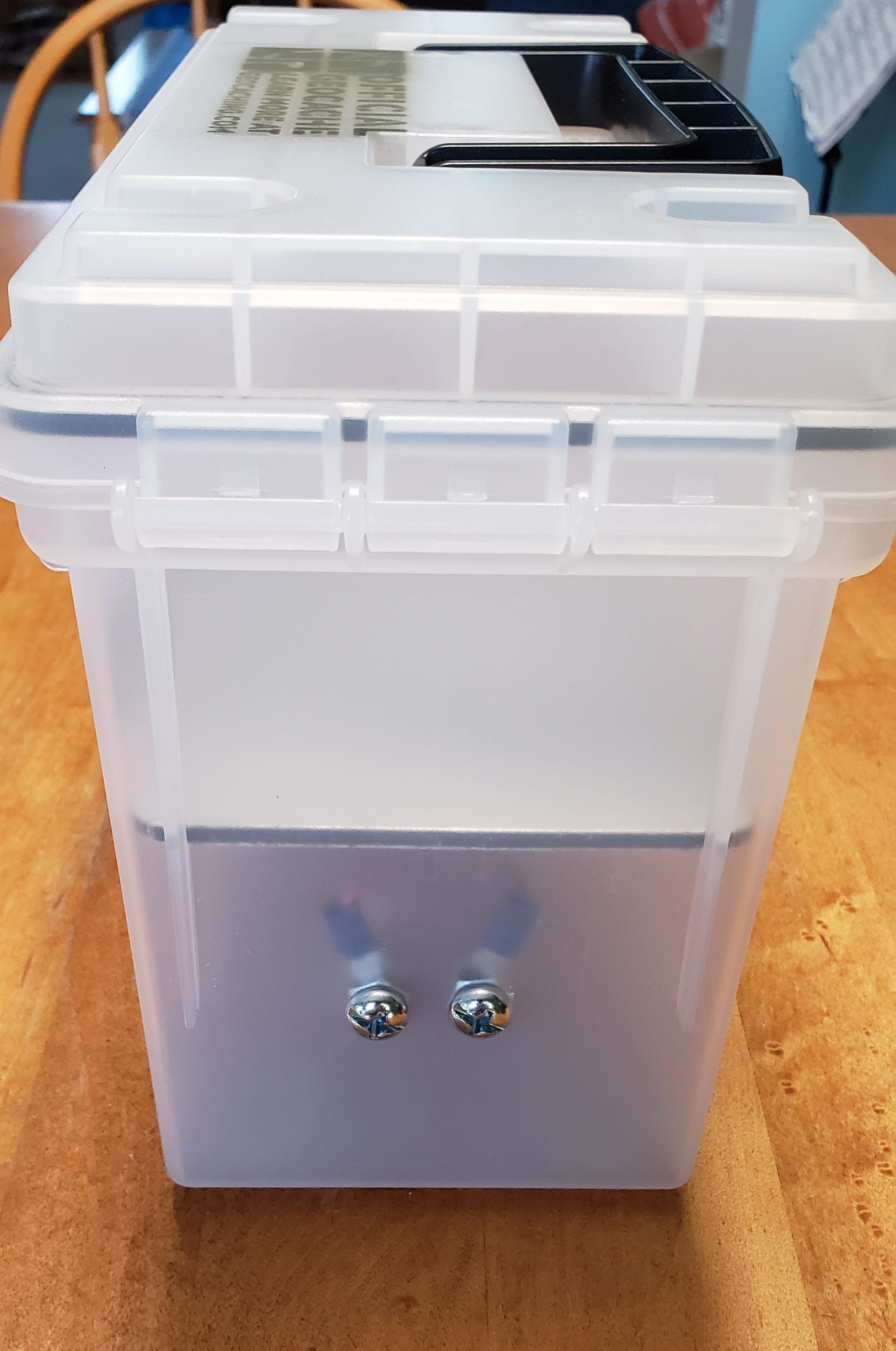
This gadget build went from experiment to finished cache when I discovered frosted clear plastic ammo cans at Wal-Mart. With a locking hasp and a rubber gasket to keep moisture out this seemed perfect for a light based gadget.
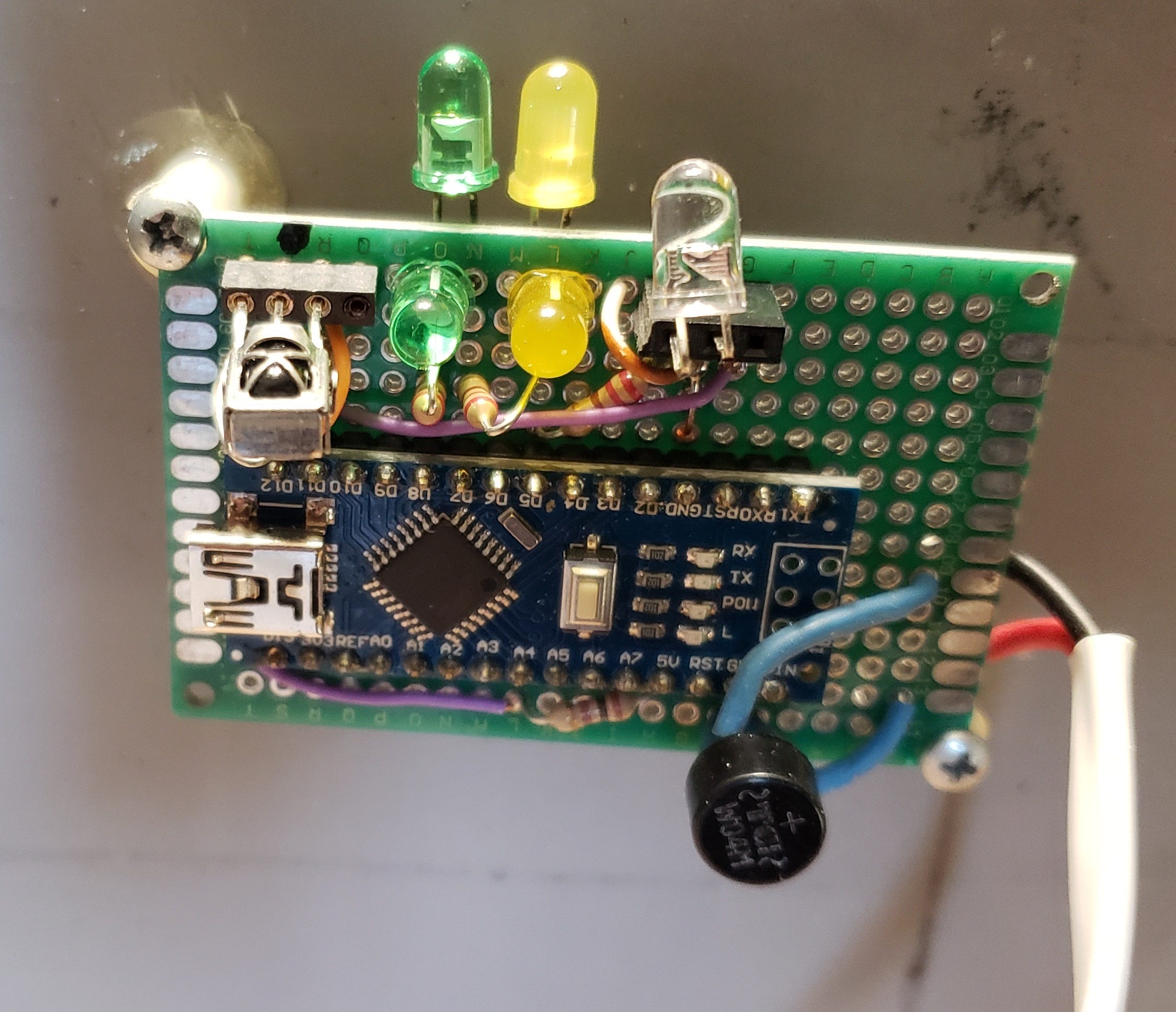
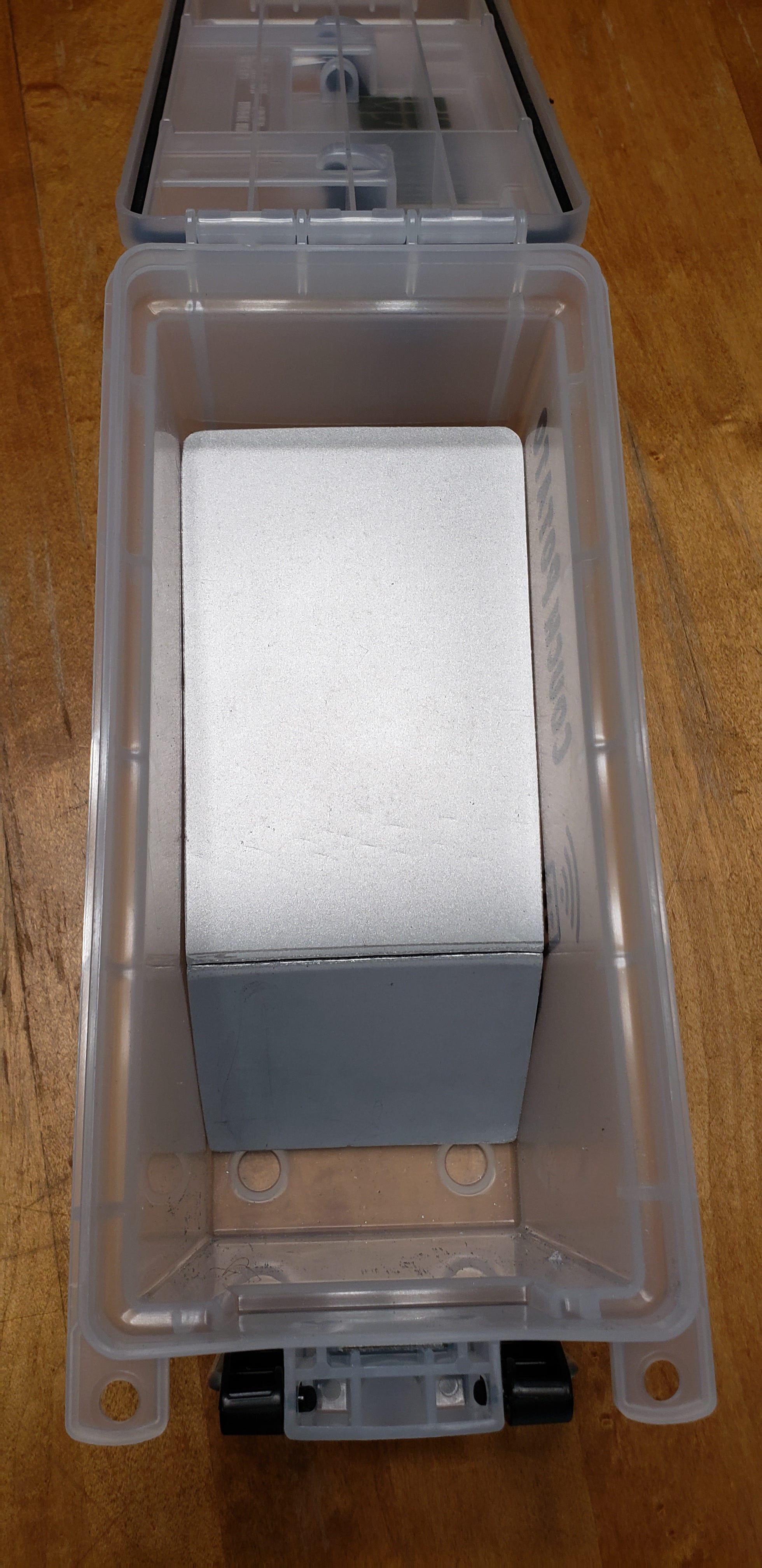
All of the components could be safely inside the ammo can since IR and visible light passes through the plastic. The circuit is mounted to the underside of the divider panel separating the puzzle from the log/swag area of the can. From left to right across the top of the board you can see:
IR sensor
Green LED
Yellow LED
Output LED
The green and yellow LEDs are for status indication and have two LEDs each so status can be seen from any direction. The output LED has a socket so I can change the LED type.
Once assembled with some silicone, the puzzle circuit will be isolated from the log and swag with the container opened.
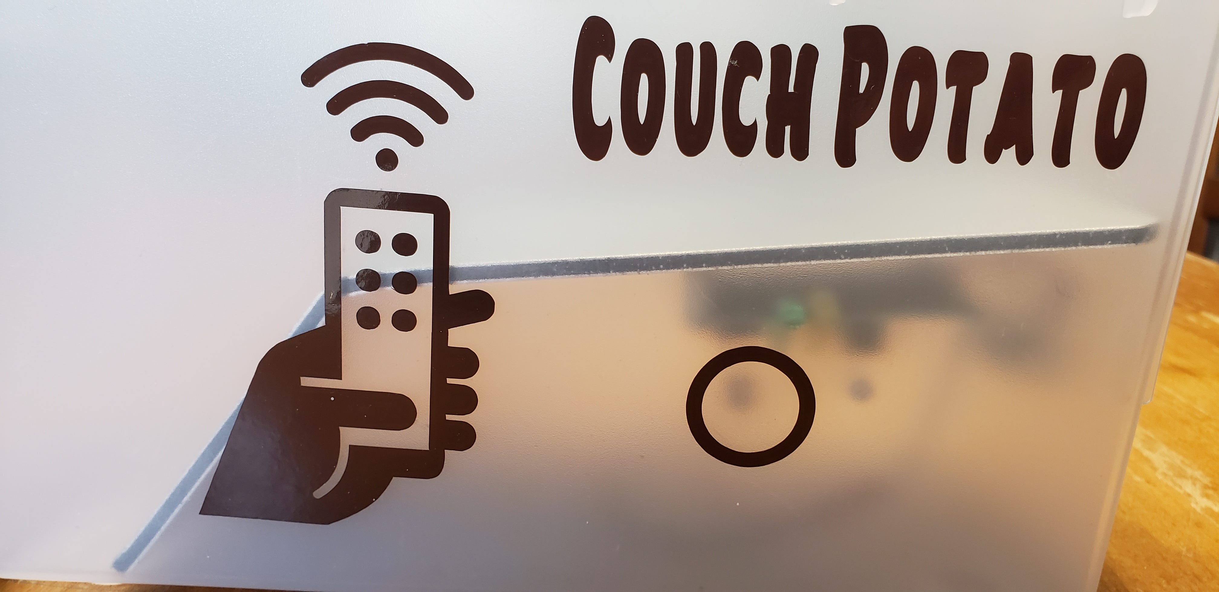
I added labels cut on the Cricut to complete the build. This should provide a hint on how to solve the puzzle. The circle shows where the receiver is located. Doesn’t everyone take a TV remote into the woods when geocaching?
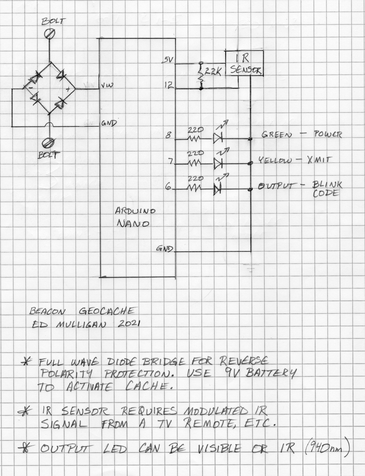
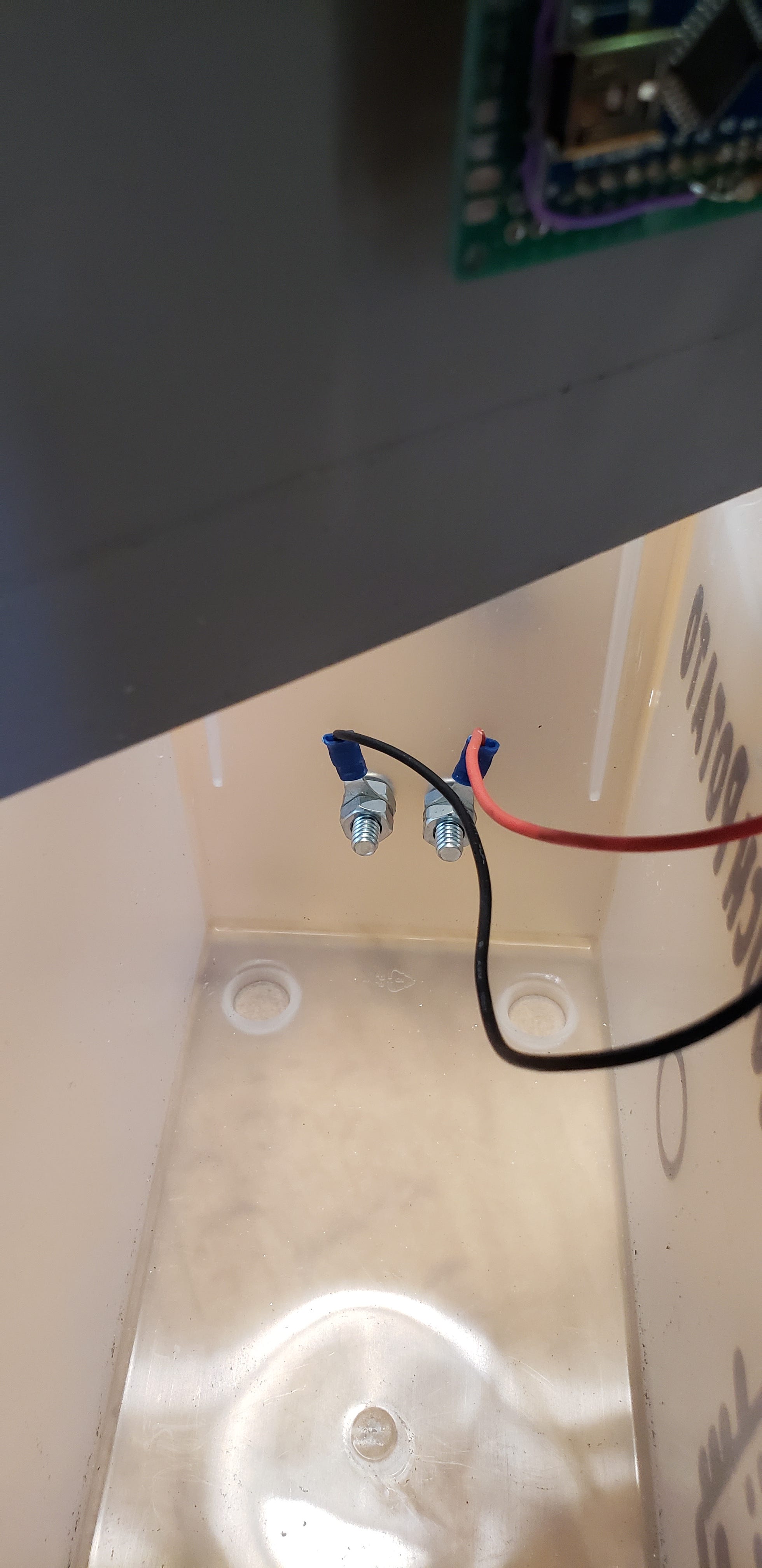
A 9V battery is the easiest way to power gadget caches that have exposed power connections. Two bolts work fine. There is no need for a fancy battery holder. The Arduino Nano runs on 5V. It has a regulator build in so that higher voltages can be used safely. To prevent damage from a battery connected backwards, I used a bridge rectifier in the circuit to provide the correct polarity no matter how the battery is connected.
Operation:
The small red LED on the nano turns on when power is applied.
When the program is running the green LED illuminates. [POWER ON]
If the modulated IR signal from a remote control is detected, the program begins its output sequence by turning on the yellow LED and keeping it on while blinking the code. [TRANSMITTING]
The output LED blinks the lock code, with larger pauses between digits.
You can find video of the cache operating on my YouTube channel.
I use a few different tools when designing gadget caches. Sometimes I start with real hardware on a breadboard, but other times I do it all in simulation using Autodesk’s Tinkercad. The circuit area of their free site allows online simulation of Arduino hardware and software. While based on an Arduino Uno, converting to a Nano is an easy process. Tinkercad allows graphical programming much like the Scratch language often used in elementary school classes. This makes it easy to get code working even if you can’t remember which libraries to include. Assemble your virtual devices, drag and drop boxes to program, and Tinkercad generates the code that you can copy to the compiler to program the Arduino. In this example you can see the circuit on the left, the block code in the center, and the text code ready for compiling on the right.
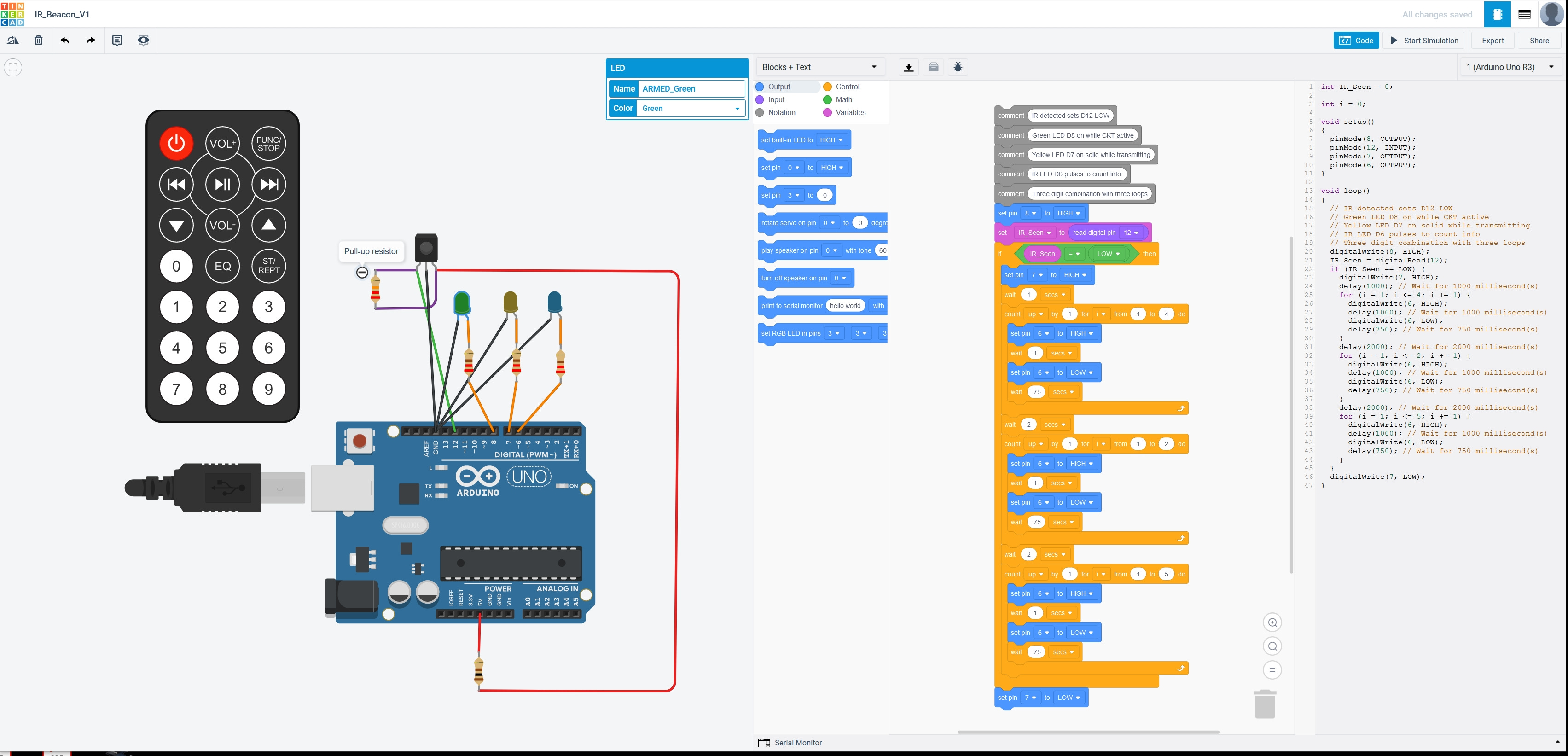
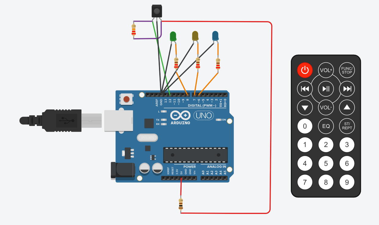
The simulated circuit is made with three LEDs, the IR receiver, and resistors as needed. The IR receiver and remote are already in the simulation environment. All I needed to do was drag and drop them onto the work area and draw lines to connect the parts.
The graphical interface is quick to learn and has block shapes designed to make the commands easy to understand. I sometimes start programming with the block environment to get all the basics right, but I often take that code and continue debugging in the native text for the Arduino, which is much like programming in C.

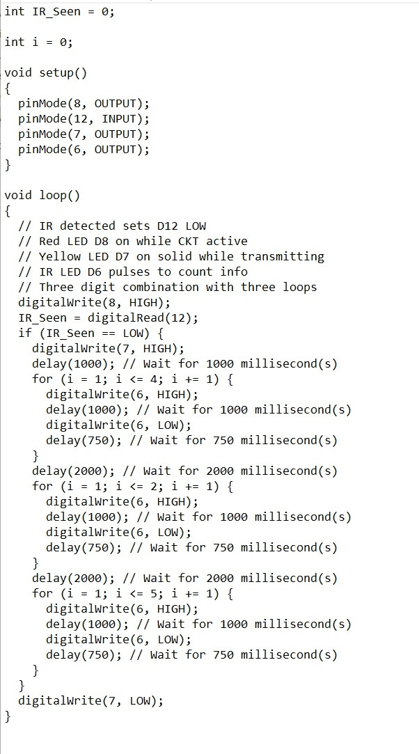
The output from Tinkercad, after my continued development and debugging, looks like this. Note the IR LED comment text in the code. That’s the output LED, with my original note on using IR for the beacon’s early design.
Always document projects with real schematics. The picture and line artwork of the simulator is fine for initial testing, but if you want to show it to others without making them guess about pin numbers, etc. please draw it in real schematic form. Here you can see the addition of the bridge rectifier (four diodes in one package) to present the correct voltage polarity to the circuit no matter how the 9V battery is connected.
If you choose to use an IR output LED, use 940nm wavelength LEDs so the output is completely invisible. Other wavelengths can have some dull red visible glow.