
There are links to parts in this article. I have no connection to any of the manufacturers or retailers, and I don’t get anything if you follow the links. I just pick things I think are fun or interesting.
While I’ve been busy with non-gadget things lately, I haven’t forgotten about the cryptid puzzle. You can expect to see more about that project soon. This article is about how I got distracted buy something shiny on a trip to a Micro Center store– a 10mm RGB LED.
With this LED and a few other parts, we can make a quick, no programming needed, color to number converter.
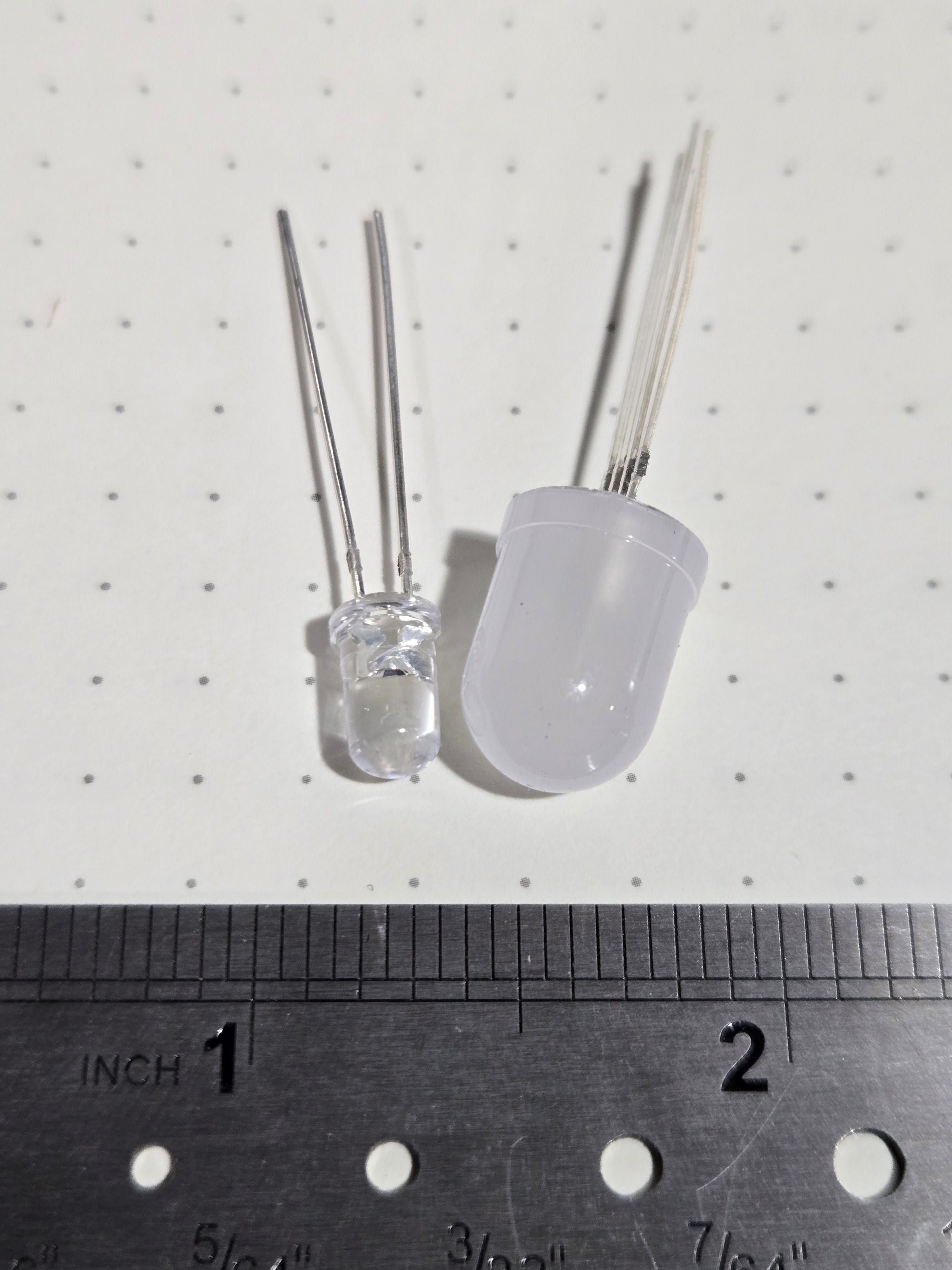
Here’s a photo of the 10mm LED next to a standard 5mm LED.
Red-Blue-Green LEDs like this have all three LED chips inside one device. Each LED chip has its own leads, with one common lead for a total of 4 wires on the device. This image from the LED’s data sheet shows what’s inside.
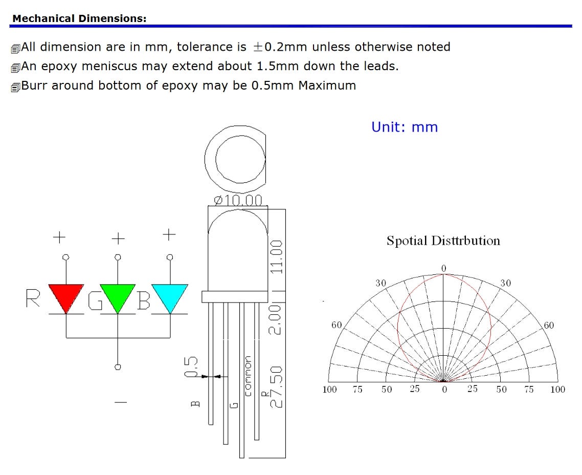
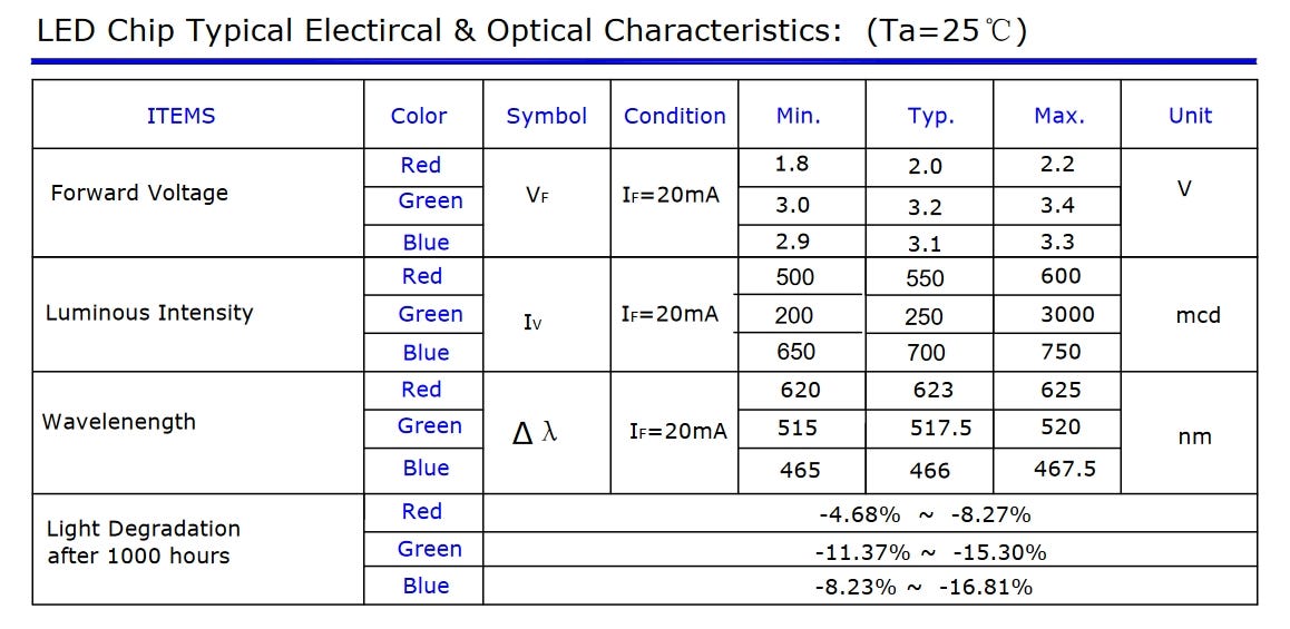
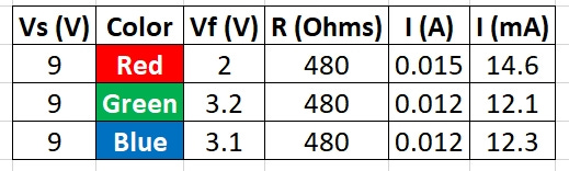
From our previous work we know we need to control the current through each LED. We do that by choosing a current limiting resistor. While we’ve covered it before, it is important to point out that each internal LED chip needs to have its current controlled individually. This means we need three resistors. If we only used one on the common lead, that would set the total current through the device, which would then divide between any parts of the device that were on. The brightness would change as we chose different combinations of colors, and we don’t want that. The other advantage of three different resistors is to adjust the brightness of each color individually to get the blends you want. Red, blue, and green LEDs are not equally efficient so some tuning may be desired, but it isn’t needed. We can see the differences In this section of the data sheet showing the different forward voltages and brightness levels (mcd) of each color in the device.
As we go forward, I’ve used the same resistor for each color in my design. Feed free to adjust as you see fit as long as you don’t go over the maximum current for your device! Here’s what I chose to keep the LED bright but not at its maximum. If you need some help with setting up the resistors for your LEDs, you can check out my earlier article or use an online resistor calculator like this one from Digi-Key. I am using a 9V battery for this project. If you have a different voltage you can adjust the calculations as needed.
Lighting up red, blue, or green only gives us three choices. We can do more than that with this LED. We can also combine colors. With three inputs we can get to seven colors plus off, making eight possible states. Does that trigger any memories from computer science class? Three things that let us count to 7? Three bits? Binary bits! If we look at the three colors as binary bits, we can get 8 states in a table like this:
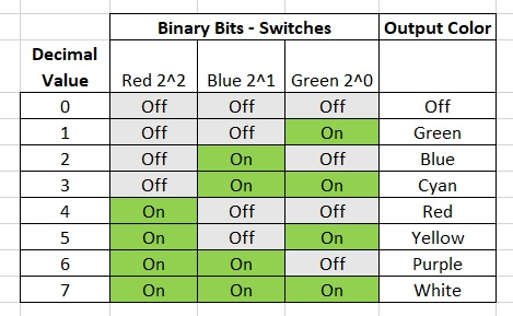
It doesn’t matter which color you use for each bit, so go ahead and make your own choices. From the table, we can see that 101 in binary, or turning on the red and green colors together, makes the LED look yellow. Binary 101 represents the number 5 in decimal. With numbers from 0 to 7 you might not be able to set up coordinates, but the combination to a lock would work well. Or, to get a 9 you could say white+blue. The goal here is simple and robust. This circuit only needs three switches, three resistors, the LED, and a battery. There are no complex parts to program or to be damaged by water or rough handling. We could stop here if you wanted cachers to do the binary in their head. That’s fine if you want to make the puzzle harder or if it better fits your overall theme.
But what if we wanted to make it easier and have the decimal numbers be visible to the cacher? We can do that without much trouble and we still won’t need to do any programming. There’s a device ready for us to use for this task – the CD4511 integrated circuit (IC). This 16 pin device takes a Binary Coded Decimal (BCD) input and then turns on the correct outputs of a 7 segment LED display. There are other decided ICs, but this one works from 3 to 15VDC, covering the range of battery powered projects. No need for a regulator to give a solid 5V like many other logic chips. Even a weak 9V battery should be fine with this project. Build Electronic Circuits has a deeper dive into the CD4511 here.
I decided to ask Google’s Gemini AI to explain the CD4511. It did a pretty good job, except for something I will discuss in a moment.
The CD4511 is a BCD (Binary-Coded Decimal) to seven-segment display driver IC. It takes a 4-bit binary coded decimal input and converts it into the appropriate signal to light up the correct segments on a seven-segment display, showing a decimal digit (0-9). Here's a breakdown of the CD4511's pins:
Power Pins:
VDD: Positive power supply input (usually 3V to 15V)
GND: Ground pin
Input Pins:
D0: Least significant bit (LSB) of the BCD input data
D1: Second least significant bit of the BCD input data
D2: Third least significant bit of the BCD input data
D3: Most significant bit (MSB) of the BCD input data
Output Pins:
a: Connects to segment "a" of the seven-segment display
b: Connects to segment "b" of the seven-segment display
c: Connects to segment "c" of the seven-segment display
d: Connects to segment "d" of the seven-segment display
e: Connects to segment "e" of the seven-segment display
f: Connects to segment "f" of the seven-segment display
g: Connects to segment "g" of the seven-segment display
Control Pins:
LT (Lamp Test): Used for testing the seven-segment display. When set LOW, all segments light up. Set HIGH for normal operation.
BL (Blanking Input): Turns off all segments of the display when set LOW. Used to blank the display for power saving or other purposes.
LE (Latch Enable): Controls when the BCD data is latched to the outputs. When HIGH, the current BCD data is latched and displayed, ignoring changes on the inputs. When LOW, the output follows the inputs.
Now for my note on using Gemini or other AI. YOU MUST CHECK THE OUTPUT! The original AI generated document had all the IC’s pin numbers wrong. The circuit would never have worked, and might have damaged the parts. The description for Latch Enable was also wrong, and would have suggested connecting it incorrectly. AI can give a good start, but always check the result. You’ve been warned.
AI does have the fun feature of asking for a document like this written as someone specific. When asked to describe the CD4511 as Cookie Monster, it replied:
Me love explain CD4511 like cookie! Me call it "number nom nom circuit" because it take numbers and make them yummy yummy on a seven segment display!
Imagine a seven segment display like a cookie with seven chocolate chunks. Each chunk light up to show different numbers. Not round cookie though! More like a rectangle with pointy bits.
I won’t torment you with the other results, but I was able to have AI generate Elmo’s version, a Metallica song about the CD4511, an Elvis version, and a long version as if written by William Falkner.
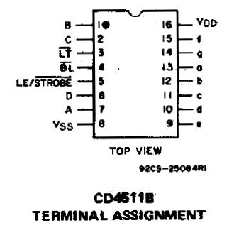
Back to the project of turning colors into numbers, or numbers into colors. We will use inputs 0, 1, and 2 since we only have three bits. Connecting the unused input to ground prevents it from causing trouble. Connect lamp test and the blanking input high so they don’t activate. Tie the latch enable to ground so it doesn’t latch the output. Here are images taken from the Fairchild and TI data sheets for the CD4511.
.
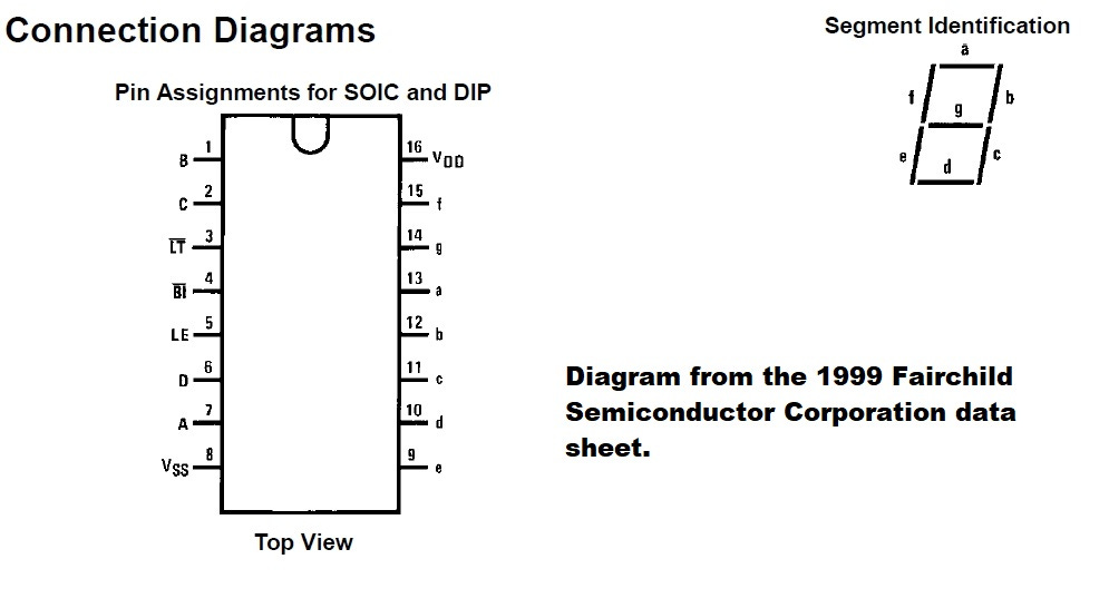
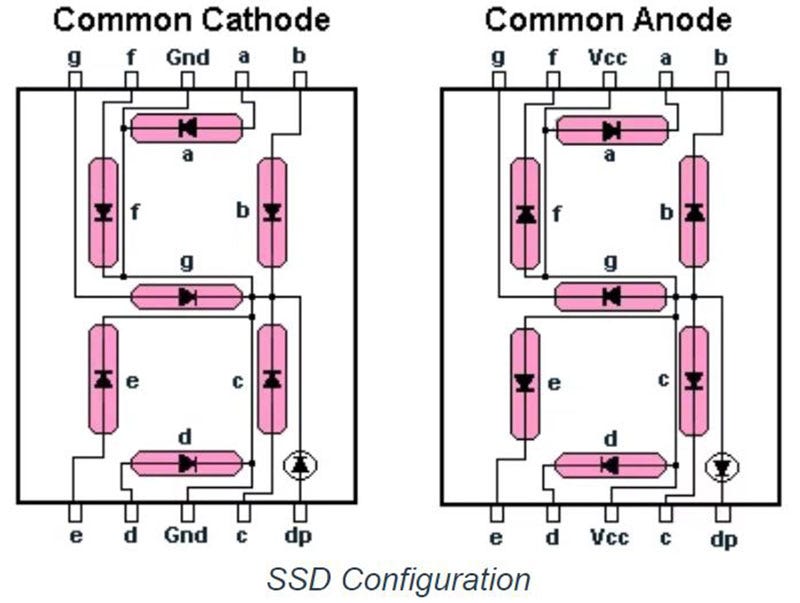
I chose a common cathode 7 segment LED display. This means that the negative side of all the LEDs inside the display are tied together, or common. Common annode displays are also available with all the positive terminals tied together. These images from Digi-Key’s excellent article on the displays show the arrangement:
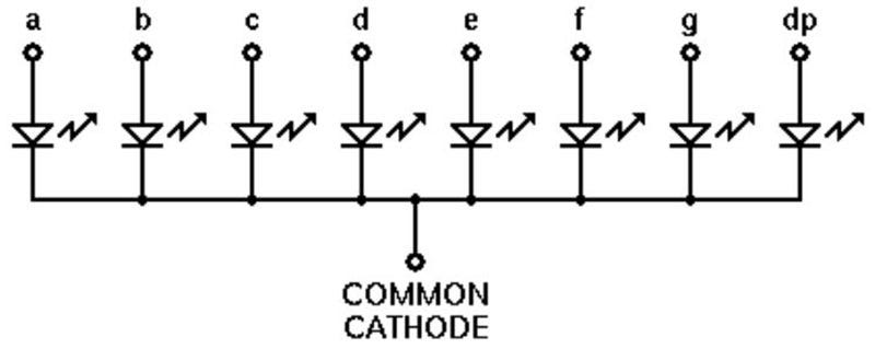
You will need to pick current limiting resistors for each of the 7 segments, just like any other LEDs. I also chose to light up the decimal point when the power is on so cachers know the gadget is working. That requires another resistor, for a total of 8.
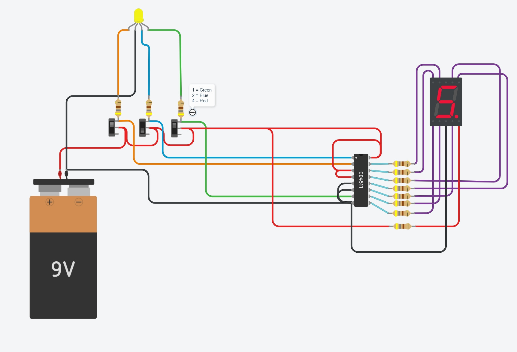
I often do hand drawn schematics for projects, but for this article I wanted to show another option – Tinkercad. Tinkercad is a free, web-based service from AutoDesk. It can do circuit modeling, help program an Arduino, and 3D modeling to make 3D printed parts. It is a powerful tool. I set up the circuit in Tinkercad and enabled simulation to test my design without any physical parts. This can be a real benefit if you don’t have the parts you need or if you don’t have space to work. It also lets you avoid damaging parts if your design is wrong.
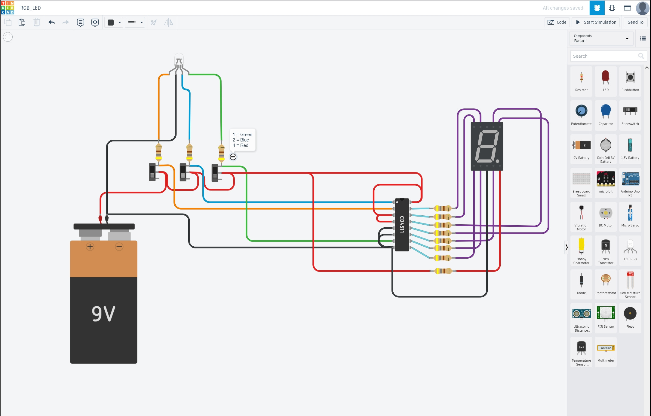
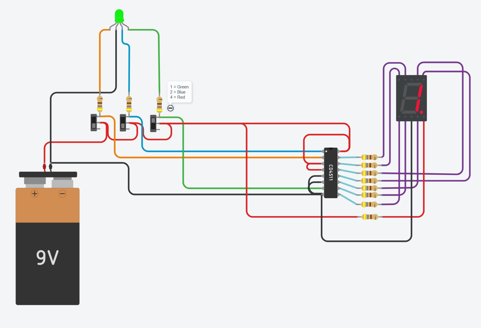
Everything we talked about is in the drawing. Three switches and resistors for the RGB LED, and then the wiring for the CD4511 and the 7-segment display. I also included a note so I would remember the binary bits each color represented. Hovering over the pins of the CD4511 shows what each pin does. The 7-segment display has the same helpful feature. Tinkercad can simulate input conditions and show the outputs. The next image is with the switches set for green followed by another showing the switches set for yellow. The LED changes color in the simulation.
This circuit would be easy to make on a small circuit board and with a little waterproofing should work well outdoors. I may use this as my test to learn how to have printed circuit boards made. Drop a comment if you would be interested in more about that idea.
What can this circuit do for a gadget cache?
· Reveal numbers for a lock from colors painted on a device, or in printed text.
· Give colors from decimal or binary numbers.
· IT could be an interface to a more complex circuit, such as playing different sounds for each color combination. A gadget could read out seven different coordinate sets for the final, but only the red one would be correct.
Have any other ideas for this circuit in your projects? Did you like circuit simulation with Tinkercad and want to see more of it? Are you working on anything interesting that you’d like to see featured on MakerCaches? Drop me a note or leave a comment.