

The first batch of parts have arrived and that means we can begin testing the design. I chose to start at the beginning of the gadget, which for the cacher is tuning the receiver to get instructions. The tuning puzzle requires matching four LEDs to the target colors using four switches. There is nothing special about using four switches as the system could work with one to as many as you like.
Any products/links in this article are to show what I purchased. I have no connection to, or benefit from, these suppliers. Images in this article are from the product listings or my photos.
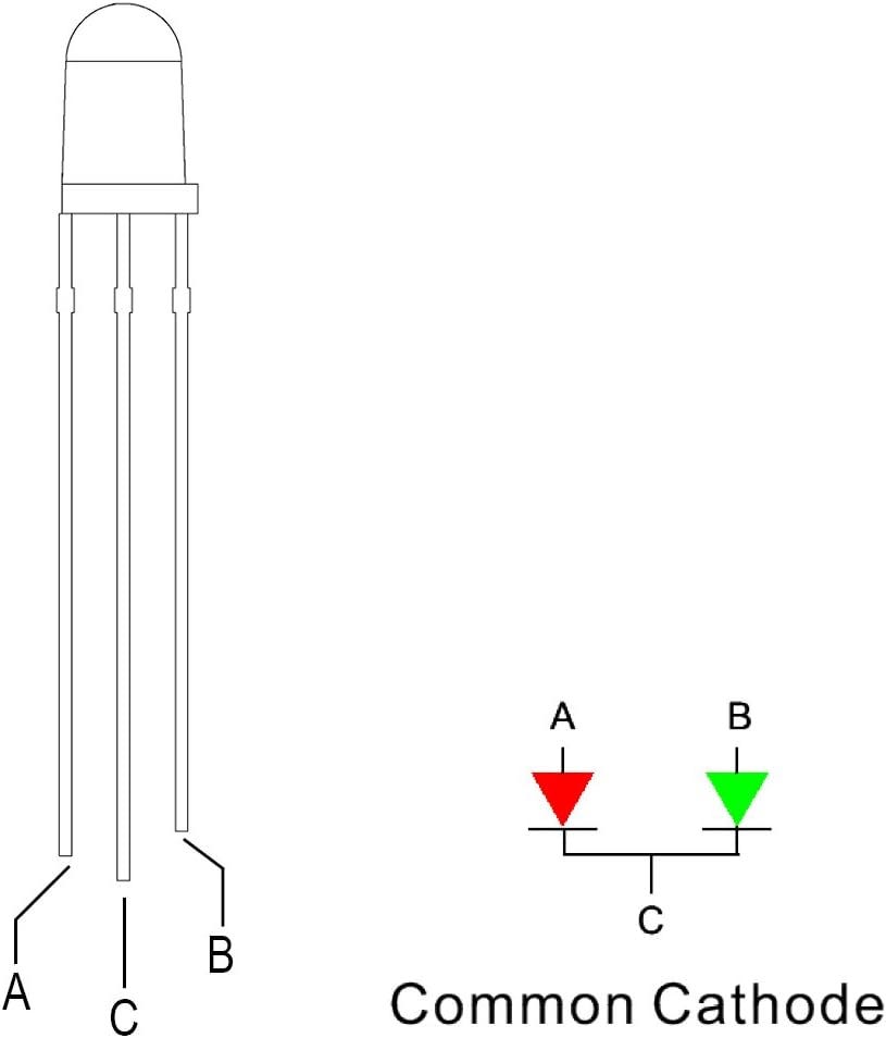
I chose these red/green common cathode LEDs because the were inexpensive and would arrive quickly along with resistors.
There are two different resistor values included because the forward voltage of the red LED is not the same as for the green LED. Red LEDs often have a lower forward voltage, in this case 2.0 to 2.2V compared to 3 to 3.2V for the green. For an equal voltage source, the red LED needs a larger resistor to drop a little more voltage when setting the current. I talked about the math needed to choose resistors in this article, but you can find many calculators on the web. If nothing else, use the included 470-ohm resistors on the red LED and the 430-ohm on the green and you will be OK up to 12V.
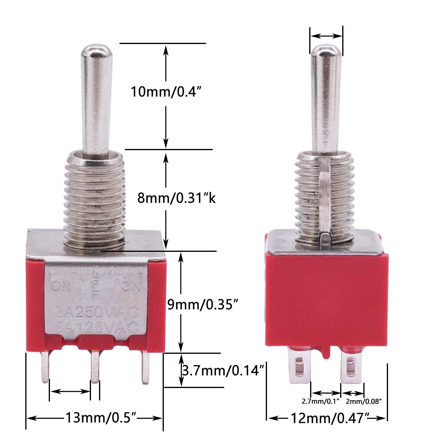
I will be using these DPDT momentary switches because they come with waterproof covers.
I like to use momentary center off switches because they make the puzzle self-resetting. I don’t want one player to leave the puzzle solved for the next. The DPDT momentary switches form a puzzle just like I did in the Maker Magic gadget, but here we do not have the finder rely on trial and error to solve the puzzle. For this build the second set of contacts are used to drive the dual color LEDs:
Switch centered = LED off
Switch in position 1 = LED green
Switch in position 2 = LED red
The finder must move the switches to positions that match the target LEDs that illuminate when power is applied. If a refresher on switches would help, you can go back to this article.
Before we look at the full schematic, it will help to go into more detail on the components.
The LEDs look like a normal water-clear LED, but they have both a red and a green LED inside. With three pins, the positive side of each internal LED is individually available and the negative side of each shares the center pin.
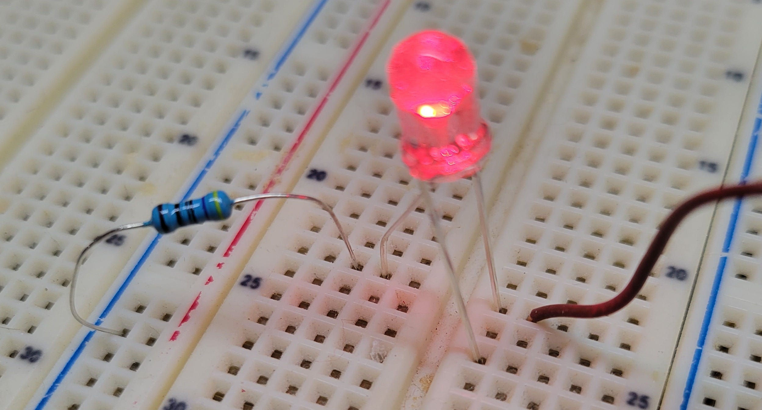
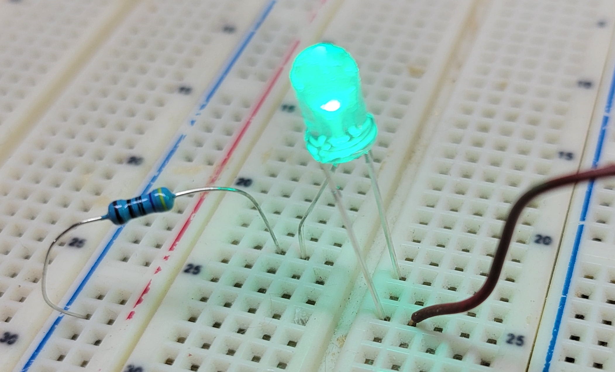
Just like using two individual LEDs, the current must be managed properly. If only one LED will ever light, as they are used in this project and in the photos above, then a single current limiting resistor can be used. If a single resistor is used when both colors are illuminated then the total current will be set by the resistor and divided between the two LEDs. This means the LEDs will be dimmer when they are both on compared to when either color is lit alone. When using both internal chips at the same time, use a properly chosen resistor on each positive connection and none on the negative side.
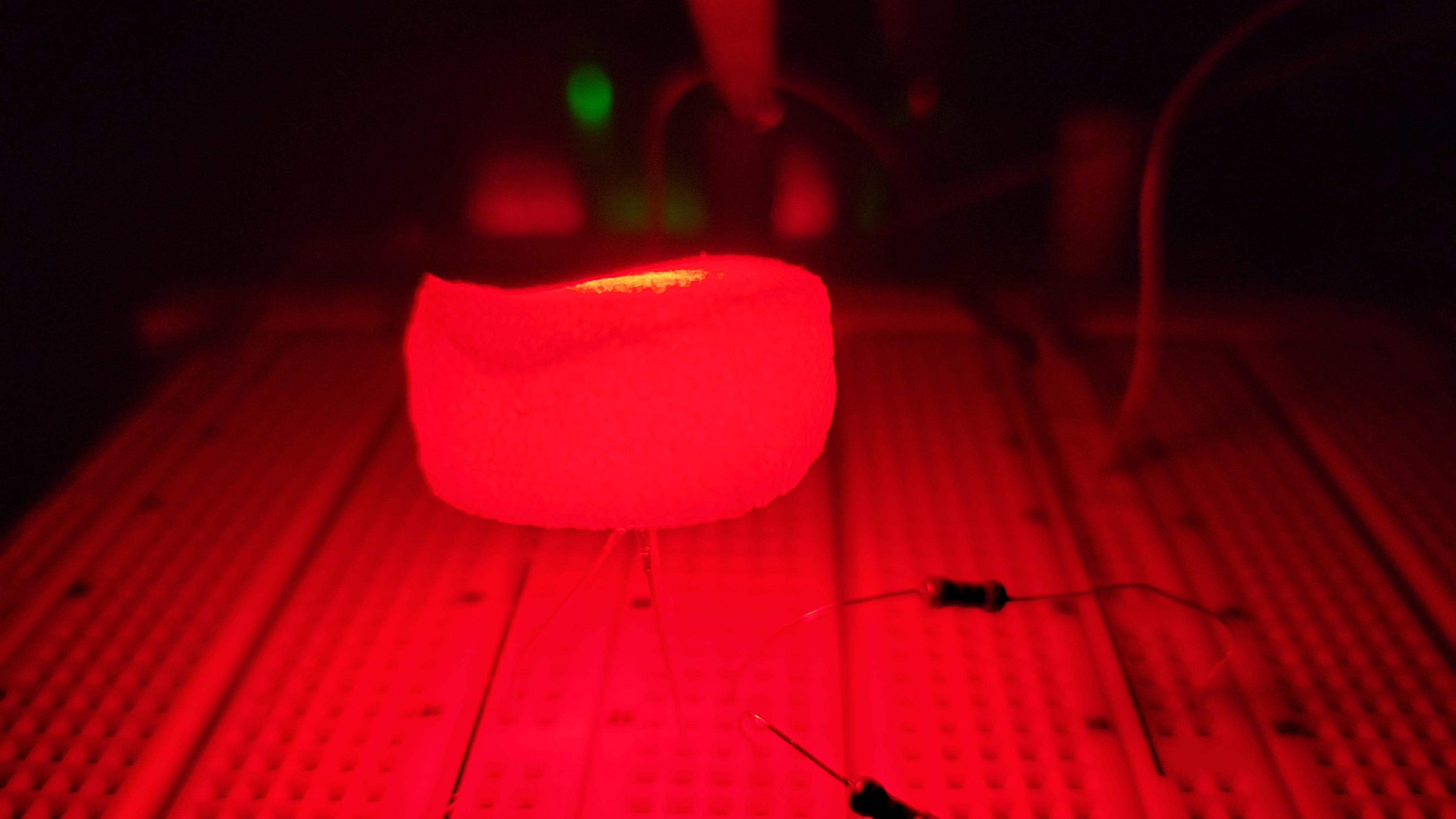
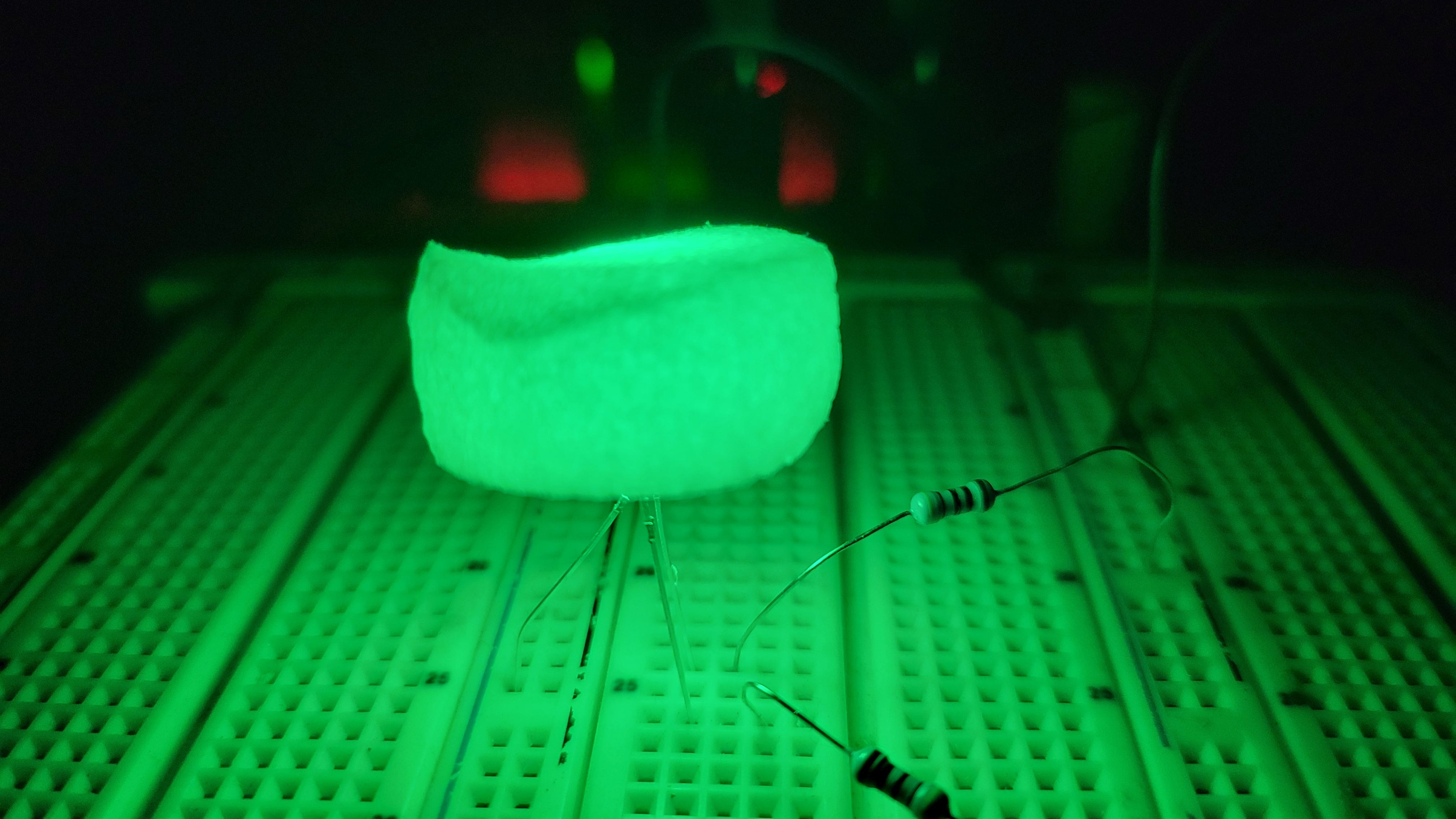
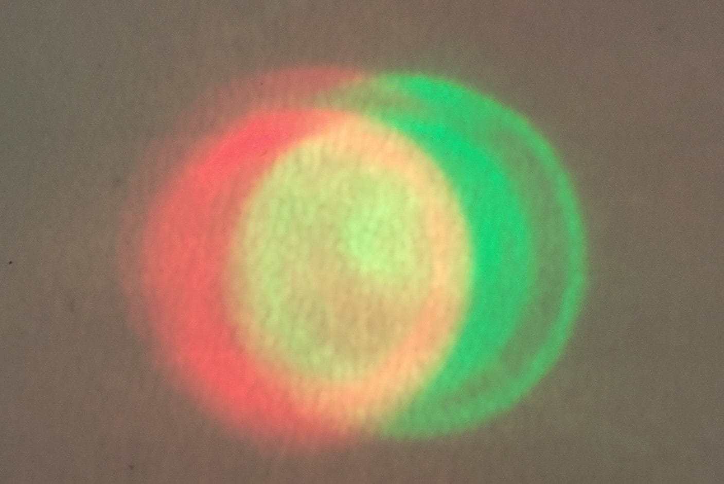
I tested the LEDs and found them to be very bright. 20mA is uncomfortable to look at, and they are visible with much less current. A fun trick of these LEDs is their use to show three colors. If the current to the red and green elements is managed properly, a red/green LED can show red, green, and yellow (both red and green lit). In the following photos, I placed a foam over the LED to make it easier to photograph the colors. The LED is fed 11.5V with a 470-ohm resistor on the red pin for 20mA, and 940 ohms on the green pin for 9mA. The green is very bright and I wanted to dim it a little for a good yellow color. Note that there are resistors for both red and green in this application.
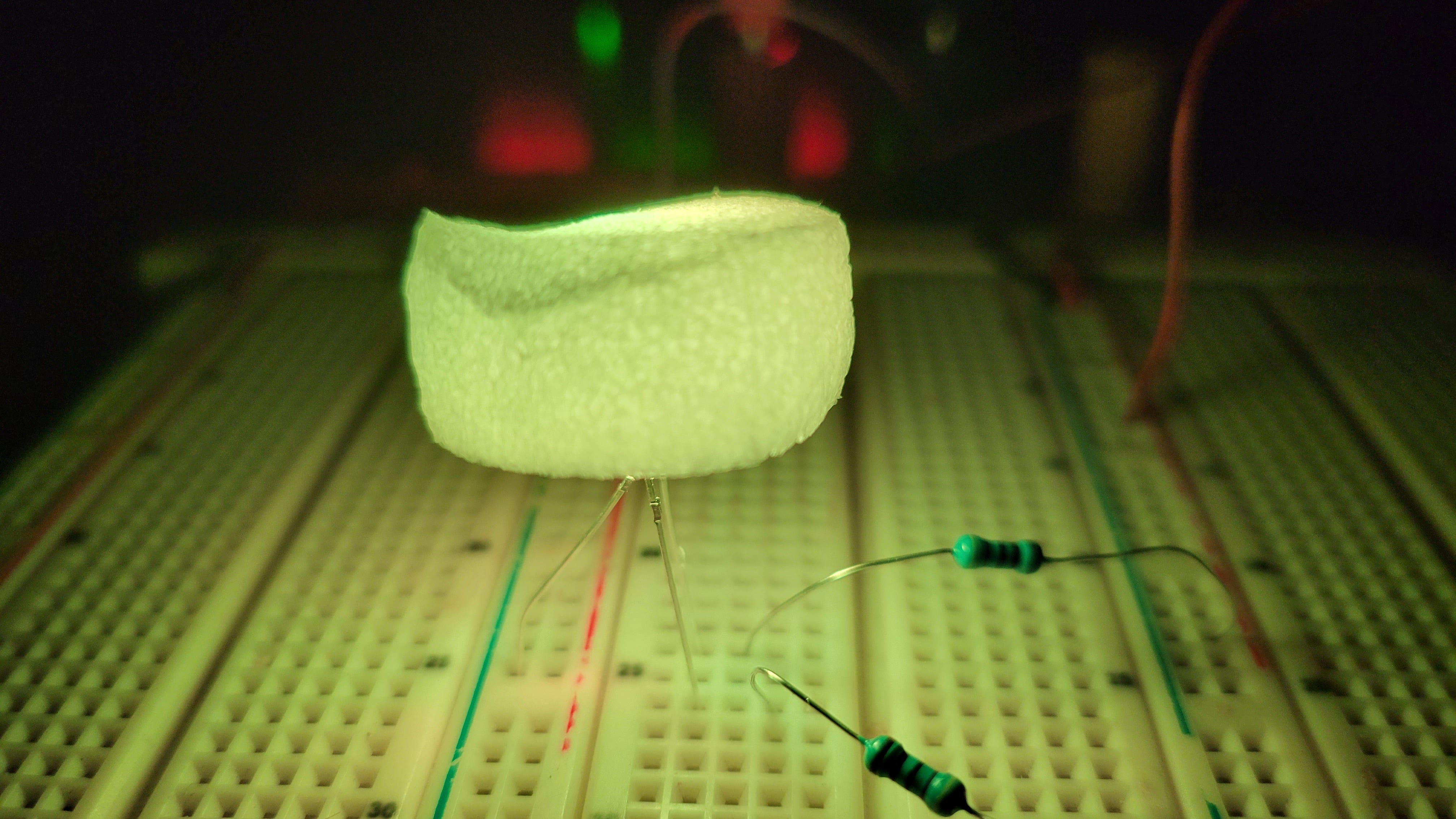
The red and green chips are next to each other inside the LED, and I was able to get a photo showing the offset by shining the light through white paper with the power reduced. It is easy to see how red + green = yellow in this photo.
The contacts on the DPDT switches are arranged in two sets of three. The center is the common terminal, and the outer two are connected when the toggle is moved. In the photo I marked one set of contacts with a yellow box and the other with a green box. Pins A, B, and C are one set with B as the common connection. D, E, and F are the independent second set with E as the common terminal.
This color coding will help keep things clear when we look at the schematic. Remember that these two sets of contacts are not electrically connected to each other. The switch acts like a pair of SPDT switches, but in the same case. Most of the time the contacts connect opposite of the toggle movement - if the toggle moves up, the lower contact will be made. Keep this in mind when mounting and wiring your switches. Always check your switches to make sure you know how they work before mounting and soldering everything.
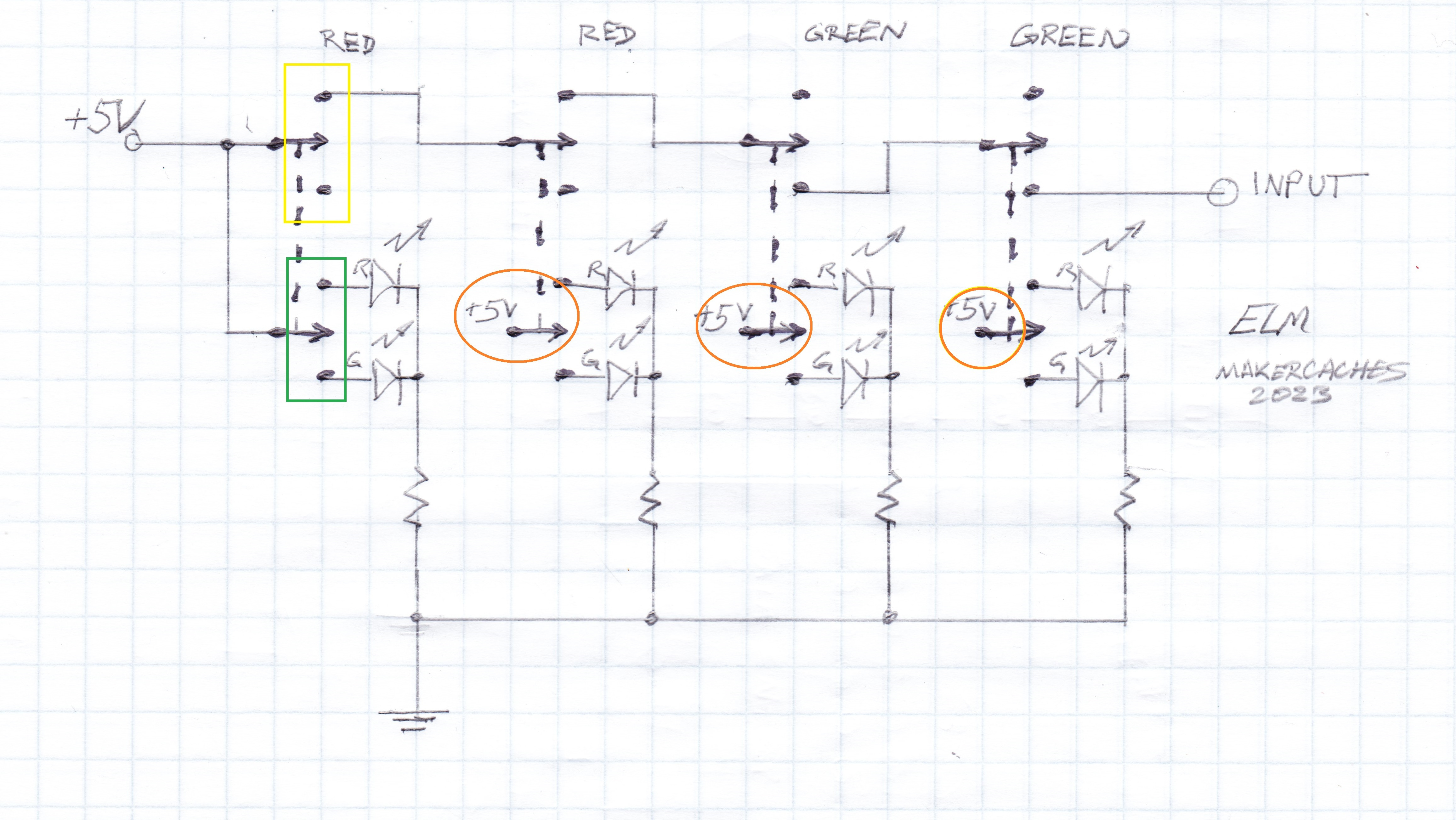
The schematic for the tuning section of the puzzle looks like this. The yellow and green boxes are shown in on the first switch matching the earlier photo to clarify the two sets of contacts. Also note the three orange circles. 5V must be applied to the center pin of each switch. To keep the drawing clear, I didn’t add lines back to a single 5V input point. If you forget these connections three of the LEDs won’t light. Choose your resistor values to get the desired brightness.
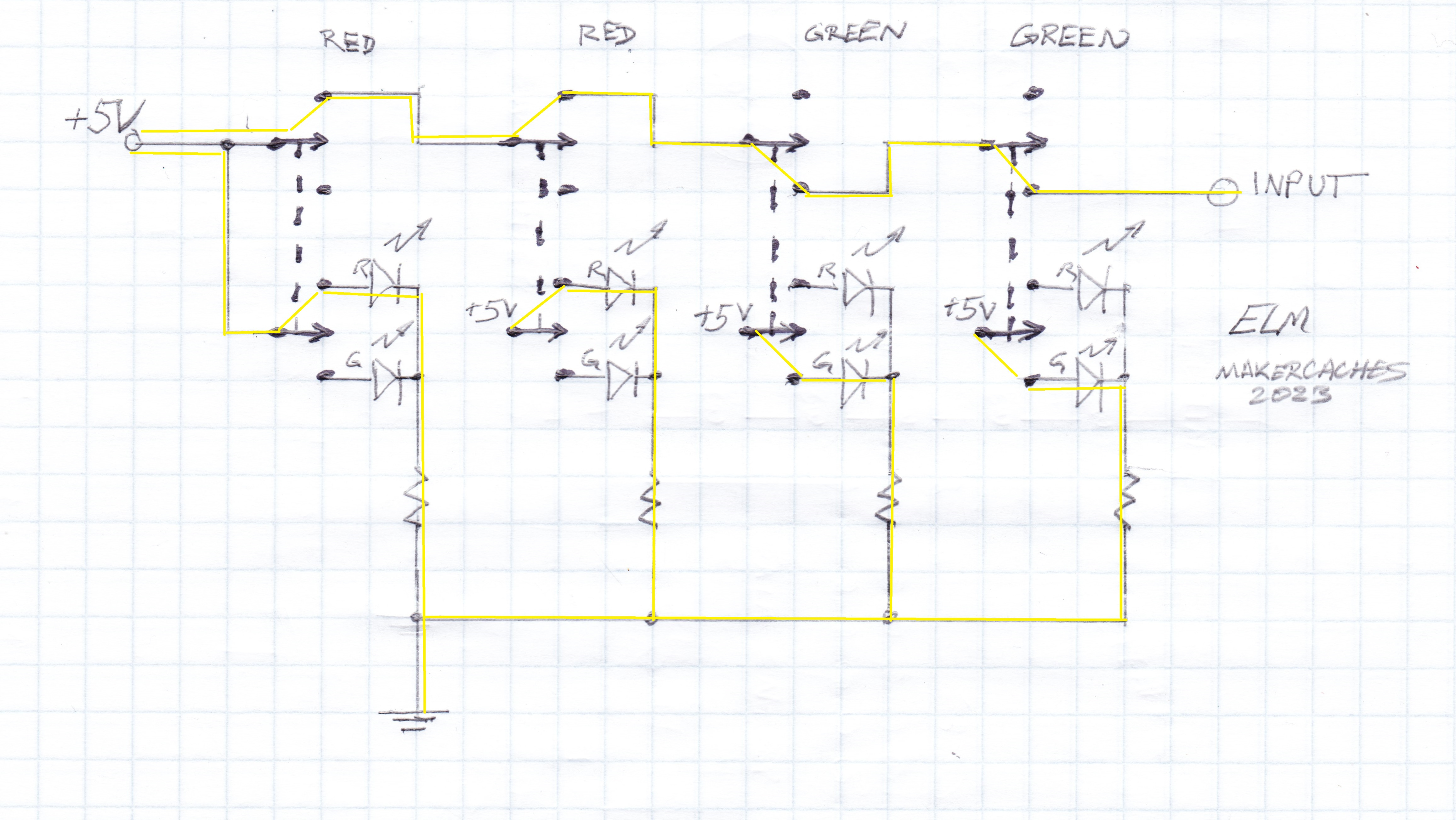
The tuning frequency to solve the puzzle for this example is down/down/up/up, which gives red/red/green/green. Each switch is shown with a dotted line between the two sets of contacts indicating they move together as a DPDT switch, not a pair of SPDT switches. The two set of contacts sends an input to the puzzle controller and light the matching LED color when the switches are in the correct position. You can follow the circuit through the system with the yellow lines added in this version.
Next time I’ll discuss the other input devices for the puzzle, the DP5T switches used to set the commanded coordinates to “communicate” with the research base.
If you have questions, please leave a comment or contact me at:
makercaches <at> substack.comI hope you will subscribe so you won’t miss new articles. If you’ve built something fun send some details and I’ll spotlight your build. I like to see what others are doing.